Quantcast
Channel: DIYcrap
Viewing all 51 articles
Browse latest View live

Timelapse #1 (Intro)

$
0
0
I denne serien skal jeg kaste meg ut i timelapse-eventyret.

Timelapse er en teknikk som i korthet går ut på lage en video i hurtigfilm. Prinsippet illustreres enklest med et eksempel. Man tar et kamera, setter det på et stativ og retter det mot et objekt av interesse. Dette objektet bør da være ett eller annet som det kan være artig å se forløpet av over tid. Dette kan for eksempel være en tomat som råtner. Man lar så kameraet ta et bilde f.eks. hvert sekund og lar dette pågå lenge nok til at den endringen (her forråtnelsen) man ønsker å observere har skjedd. Deretter settes disse  enkeltbildene, som gjerne blir flere tusen, sammen til en film. Når denne filmen spilles av med 25 bilder per sekund spilles forløpet av i 25 ganger normal hastighet. Tar man et bilde hvert tiende sekund, vil filmen spilles av i 250 ganger normal hastighet, osv. For å se forløpet av en tomat som råtner vil man måtte øke tempoet enda mer enn dette.


Eksempel over viser en av de mange flotte Timelapse-videoene som ligger ute på nettet.

En (av mange) utfordringer med denne teknikken er at de færreste kameraer har noen funksjonalitet for å ta bilde med faste intervaller. Når man først har anskaffet seg et digitalt speilreflekskamera og en bag full med kostbar optikk er det heller ikke bare å bytte til det merket eller den modellen som har Timelapse-funksjonalitet.

Jeg har et Nikon D90, som har vært en trofast følgesvenn i fire år, og har ingen intensjon om å bytte ut dette. Løsningen for å komme seg inn i timelapse-eventyret er derfor en av disse:

  1. Å manuelt aktivere lukkeren hvert X sekund. Dette vil for det første raskt kunne føre til innleggelse på en eller annen klinikk, siden det kreves at man er fysisk til stede under hele opptaket følger klokken til punkt og prikke og presser utløserknappen omhyggelig hvert X sekund. For det andre vil det kunne føre til at kameraet forflytter seg bittelitt, noe som kan spolere hele opptaket. Dette alternativet utgår av denne grunn. Dessuten er det ikke nerdete nok.
  2. Man kan benytte en PC/MAC og styre kameraet over USB. Selv har jeg forsøkt Sofortbild for MAC. Dette er en løsning som i og for seg fungerer, men er veldig begrensende i og med at man må ha med seg datamaskinen med nok batterier til å gjennomføre hele opptaket. Dette kan ta timer. Etter å ha prøvd det, syntes jeg heller ikke at det ble veldig stabilt. Av og til stoppet hele opptaket.
  3. Det tredje alternativet er å kjøpe et intervalometer. Dette kobler man på en port på kameraet, stiller inn på valgt interval, og fyrer løs. Det finnes både kostbare (1495kr) og ganske rimelige ($23.9) enheter på markedet. Hvis man skal ta timelapse-hobbyen til et høyt nivå, kan det være at det er noen funksjoner man skulle ønske at disse enhetene hadde. For eksempel bulb-ramping eller styring av en slede. Men den største ulempen er selvsagt at dette ikke er nerdete nok. Man går da ikke hen og kjøper en billig dings man kan lage mye dyrere selv?
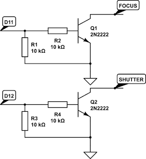
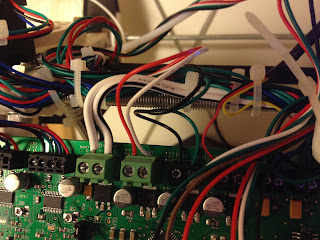
  4. Alternativ fire er naturlig nok å lage timelapse-enheten selv. Dette er det eneste alternativet som sikrer ønsket resultat og gir nok nerde-kred.
I neste bloggpost vil jeg presentere hvordan man kan lage sin eget intervalometer. Følg med!


Timelapse #2 (Bygging)

$
0
0

Dette er del to i timelapseopplegget. Del 1 finner du her. I denne delen skal jeg beskrive hvordan man kan lage et eget intervalometer til Nikon D90.

Det finnes to fremgangsmåter for å styre kameraet. Den ene varianten styrer kameraet med en IR-diode som i dette eksempelet. Den andre metoden, og den som jeg foretrekker, er å benytte en kabel som kobles til kameraet i GPS-porten. Jeg tok utgangspunkt i metoden som nevnt på instructables.

Her er de komponentene som jeg brukte:

Dette ble tilsammen ca 230 kroner. Man kan komme enda billigere unna (halv pris) ved å bruke en Arduino Nano, og justere intervallet med et potmeter istedet for med knapper og LCD. En annen fordel med dette er at løsningen vil ta mindre plass og bruke mindre strøm. Uansett hva man velger blir grensesnittet til kameraet det samme. Dette grensesnittet lages enkelt ved å klippe i trådutløseren og få rede på hvilke ledninger er henholdsvis fokus, lukker og jord. I den kabelen jeg kjøpte var sort fokus, rød lukker og hvit jord.

Når det er gjort, er det bare å trekke henholdsvis fokus og lukker til jord med et par transistorer. Disse styres så av to pinner fra mikrokontrolleren. Det som er viktig er å aktivere fokus før lukkeren.

Kameraet styres enkelt med en mikrokontroller og to transistorer.


Det kan være lurt å bruke et breadboard for å teste en krets første gangen. Iallefall om man er litt usikker på hvilke ledninger som skal hvor.

Første prototyp montert på breadboard kommuniserer fint med Nikon D90

Koden som trengs for å aktivere fokus og lukker er så enkel som dette (detaljer kan du finne her):


digitalWrite(focusPin,HIGH);
delay(10);
digitalWrite(shutterPin,HIGH);


Når kretsen fungerer på et breadboard er det bare å lodde det hele sammen. Jeg valgte et perfboard i passende størrelse og loddet av hjertens lyst.


Arduino med display og en enkel loddet krets
Så er det bare å putte herligheten i en passende boks, og dermed er det ferdig. Jeg brukte en liten boks fra Jernia som hadde pakning og det hele og skar passende hull til kabling. 


Ikke spesielt vakkert, men det er noenlunde vanntett og støtsikkert.

Siden Arduino UNO-kortet kan drives med 5V fra USB gjorde jeg strømforsyningsdelen enkel ved å benytte et USB-batteri, du vet, et sånt som man lader mobiltelefonen med når man er på tur. Dette fungerte utmerket.

Kildekoden til min prototyp ligger her. Den er veldig uferdig, og menysystemet, som er ganske amatørmessig kodet, representerer brorparten av koden. Jeg har forberedt koden slik at man kan sette maks antall bilder. Planen er også å legge inn annen funksjonalitet etterhvert, men til nå er det kun mulig å justere intervallet.

Dersom du har tips til forbedringer eller annet, kommenter under. Etterhvert skal jeg legge ut noen filmsnutter som er produsert med intervalometeret.


Timelapse #3 (Fotografering)

$
0
0
Dette er del tre i timelapse-eventyret mitt. Del en ga en generell oversikt mens del to omhandlet bygging av en egen timelapse enhet (eller intervalometer) for å styre et Nikon speilreflekskamera.


På videoen over vises mitt første forsøk med timelapse. Kameraet ble plassert på verandaen og mitt DIY-intervalometer ble stilt inn på 15s interval. Opptaket startet klokken 18:34 og gikk til batteriet på kameraet gikk tomt klokken 01:35 syv timer senere. Da hadde jeg i alt 1276 bilder.

For å unngå flimring i timelapse-videoer bør kameraet stilles inn på manuell fokus, manuell eksponering, og manuell hvitbalanse. Manuell eksponering er imidlertid temmelig ugunsting dersom lysforholdene endrer seg gjennom forløpet. Jeg valgte å stille inn kameraet på blenderprioritet. Første bildet i serien ble dermed 1/4000s (noe overeksponert) mens siste bilde før batteriet takket for seg ble tatt med en lukkertid på 30s. Lukkertiden ble dermed etterhvert lengre enn intervaltiden. Dette førte til at antall bilder per minutt gikk ned fra 4 i starten til 2 i slutten. Dette fenomenet kan observeres som en hastighetsøkning ved ca 0.46 i videoen.

Med automatisk lukkertid er det vanskelig å unngå flimring i videoen. Jeg brukte Sequence for å lage selve videofilmen. Dette programmet har en deflicker-funksjon som fungerer ganske greit. Dette skal jeg teste mer.

Jeg valgte til slutt å legge på noe musikk med iMovie. Det finnes så klart både bedre og mer egnet musikk, men jeg valgte kjapt og greit fra en side som tilbyr creative-commons musikk: http://freemusicforvideos.com

Det som var litt synd med denne videoen var at kamerabatteriet tok slutt idet stjernene kom frem og gjorde scenen spennende.  "Future work" blir nå å lage en løsning som gjør at kameraet kan drives fra et eksternt og mye større batteri.

Day to night to day timelapse

$
0
0
Recently I created a timelapse of a day-to-night-to-day transition. I used my Nikon D90 on Aperture priority and a ND8 filter. To assemble the timelapse, i used Frosthaus Sequence. Although the video is slightly boring, and there is no music, I am still quite satisfied with the result.


Entering the era of 3D printing

$
0
0
I started reading intensively about 3d-printing in March this year and I was surprised about how far this field had gotten since last time I checked (it was in 2007). In fact, I was very impressed about the quality of the printed parts mere hobbyists got. Hence, it did not take me long before I ordered a kit.

I decided to build a small printer as my first printer, and considered both the new Printrbot jr and the Reprappro Huxley. The Printrbot both looks better and is probably easier to build, being built from lazercut plywood rather than treaded rods. It is also cheaper. Nevertheless, I ordered a Huxley.


Reprappro Huxley (image from Reprappro)


The Huxley arrived after about a week and I have nothing but good things to say about the kit and the service minded folks at Reprappro. Every bag of parts is clearly marked, and with the assembly instructions on the wiki it is a joy to put together. Look here for a unboxing video by mr Mike H.

In short, I had no problems at all putting the printer together. The entire process was easy and straightforward and I can highly recommend the kit from Reprappro. Well, actually, there was one problem: The Y-axis belt tensioner is a poor design and it is very difficult to adjust the tension on the belt using the set-screw. Fortunately there are better designs on thingiverse and I will switch to this design whenever I have to remove the bed. In the meantime, I invented my own quick-fix by using a M6 bolt as a belt tensioner beneath the bed.

Using a M6 bolt as a belt tensioner for the Y-axis


The only major problem that occurred before my first print was to get the software working. As I am running a rather old version of Mac OS (10.5). I had problems with the latest versions of Pronterface and Slic3r. In order to make this combo work with the printer, I had to install Ubuntu Linux on my mac. Thanks to this guide, I managed to make dual-boot work after some struggle. In total, I think I ended up spending more time on the software than on actually building the printer. Building the printer was also way more fun.

They say that the first things you will print with your new 3D-printer are modifications for the printer. For me, this was proven to be true. I started straight away to modify the printer. First, I added a fan to cool small parts while printing. It seems to be a handy add-on that most Reprappers recommend. The fan is suppported in Slic3r, which produces the G-codes to start and stop the fan automatically when needed. I created a fan mount for the X-axis in OpenSCAD. It seems to work very well and small parts now prints a bit better. Although others have created better designs than my primitive fan mount solution, such as this one,  I think I will stick to my design for a while.

A bracket for mounting a fan on the X-axis

The other modification I have done is to control the hot-end-fan via firmware. The reason for this is that my extruder fan (which is connected to +19V constantly) is very noisy, and the fan is not needed unless the hot end heater block is on. The noise from the fan can be very annoying during e.g., calibration or when performing other hacks. I added some code lines to the Marlin firmware to make the fan switch on when the hot end temperature is above 50 degrees C. I found the necessary code lines for the Marlin firmware here, and pasted them into my own firmware. On the Huxley, the mosfet-output for the heated bed is not used, so I altered the firmware to use this output to control the hot-end fan. Now, the printer is very silent when it is not printing.

The hot-end fan is connected to the unused heated-bed output and is controlled by Marlin

The third modification I have done is to add a LCD and a rotary encoder. I could have just ordered the nice Panelolu 2, but I decided to go cheapskate and ordered a 16x4 I2C LCD and a rotary encoder from dx.com. The display uses the PCA8574 I2C I/O Expander. I spent some hours hacking the firmware, but I finally got it up and running. To make it work, I had to scrap the reprappro version of Marlin in favor of the t3dp3d Marlin version. I used the excellent guilde at Think3dPrint3d to make the display work. 


My four-line display attached in a bad printed Panelou 2-case.


It is very handy to be able to control the printer without a computer attached. I printed the Panelolu case from Think3dPrint3d. The print did not come out well,  but I will use it until I have designed a casing that is more suitable for the Huxley. For now it is mounted with zip-ties on one of the z-axis motors.


This is how my Reprap Huxley looks today.


Thats it for now. I am happy to be a part of the Reprap community, and I will hopefully print a lot of useful stuff in the future. Even if the parts that are printed sometimes come out as crap, it is still very intriguing to watch the printer produce 3d-objects.

I2C display and rotary encoder on Melzi

$
0
0
Recently, I built a Reprappro Huxley 3d-printer, and I wrote a summary about the build-process in this post. One of the modifications I have done on the printer is to add a display and a rotary encoder.

My 20x4 display and rotary encoder in a Panelolu casing

The very best solution to make a display work with the printer would be of the Reprappro version of Marlin could support I2C displays directly. However, it does not, and all my attempts to add the necessary display-code to their version failed. Thanks to the guide at Think3dPrint3d I managed to make the display and the rotary encoder work by using the T3P3-version of Marlin instead of the Reprappro version.

Display

I chose a simple I2C-display from dx.com (Deal Extreme). It comes with a PCA8574-compatible I2C-port expander. Luckily, the RA_CONTROL_PANEL, which is supported by the firmware, uses the same expander. All you have to do to make the dx.com display work is to define the RA_CONTROL_PANEL in Configuration.h in Marlin as such:


#define RA_CONTROL_PANEL

#if defined(RA_CONTROL_PANEL)
 #define ULTIPANEL
 #define NEWPANEL
 #define LCD_I2C_TYPE_PCA8574
 #define LCD_I2C_ADDRESS 0x27 // I2C Address of the port expander
#endif


It is pretty straightforward to connect the Display to Melzi:
  • GND connects to a free GND pin
  • VCC connects to a free VCC pin
  • SDA connects to SDA
  • SCL connects to SCL

Rotary Encoder

The rotary encoder I use is also from Deal Extreme. In order to make it work I had to define which pins to use in Pins.h. Look for the definitions for the Melzi-board (number 63) in the file.

//The encoder and click button
     #define BTN_EN1 11 
     #define BTN_EN2 10
     #define BTN_ENC 29

In addition i had to move the connection for the heated bed Mosfet to make the encoder work.

#define HEATER_BED_PIN     30 

I think, but I am not quite sure, that the rotary encoder must use Interrupt pins 10 and 11 in order to work. I tried different configurations without moving the heated bed connection, but the above is the only configuration which made sense (and worked).

To connect the rotary encoder to Melzi:
  • A connects to TX1
  • B connects to RX1
  • SW connects to A2
  • VCC connects to VCC
  • GND connects to GND
Thats it. The panelolu2-case is great by itself, but it is not superduper for the Huxley. If you find or create a display casing that fits above the Melzi board or fits the Huxley better, please spread the word below.


Bathroom ventilation using an Arduino

$
0
0

Introduction

 
High humidity levels in your bathroom can lead to a fertile breeding ground for microbes like bacteria, mold and mildew. This can trigger allergic or other respiratory problem. Additionally, humidity can also significantly reduce the lifespan of thematerials used in the bathroom. In my house I have a air handling unit with rotor exchanger (Flexit SL4 R) which sucks air from the bathroom (among other rooms) and blows fresh air into the house.

Flexit SL4 R air handling unit (image from Flexit.com)

However, in order to make this unit efficiently eliminate excess moisture from the bathroom when e.g., taking a shower, I need to adjust the fan speed to its maximum before going into the shower. Since there is some manual labor involved in pushing the button, it is often forgotten, and hence, the bathroom is not proper ventilated.

The obvious solution to this problem would be to control the air handling unit with a humidity sensor placed in the bathroom. There are two problems with this approach: 
  1. Setting the thresholds for increasing and lowering the fan speed is very difficult since the relative humidity can vary a lot during the year. I.e., when it is very moist, the fan might stay on continuously without being able to reduce the humidity in the bathroom.
  2. The optimal place for the sensor would be in the roof, which is very visible.

A temperature-based approach


So I thought, what is the root cause of humidity in the bathroom?: Well, it is hot water. Hence, I did a test by measuring the temperature of the hot water going through the pipes into the bathroom while taking a shower. At the same time, I also measured the humidity in the bathroom.


Humidity (in %)  in the bathroom and water pipe temperature (in C) while taking a shower (the shower lasted from minute 5-15 in the figure)


Not surprisingly, there is a correlation between the temperature of the water into the bathroom and the humidity in the bathroom. The next step is to construct a device that measures the temperature and communicates with the Flexit air handling unit. This will let the Flexit unit increase the fan speed whenever a hot shower is taking place.

Temperature sensor on the hot water pipe

The Arduino-build


Since I wanted a solution with no visible cables or boxes, I decides to go wireless. Luckily, my local DIY-shop (Clas Ohlson), has a wireless 433Mhz temperature sensor (36-1797) which costs close to nothing.

ESIC Temperature sensor from Clas Ohlson


In addition I bought a 433Mhz receiver from Deal Extreme. It is a peculiar unit since it has a lot of pins I do not understand whats for and as typical for Deal Extreme is does not ship with any sort of documentation. Nevertheless, all I needed was VCC, GND and DATA. The latter connection does not come with a soldered pin and I really do not know why. (Typical Deal Extreme confusion). However, it is straightforward to see that the receiver and the data-pin works by connecting it to a scope.

Based on this guide (which is again based on this guide) it was easy to receive sensible information from the temperature sensor via 433Mhz on the Arduino

I decided to use a Arduino Nano (ehrmm... clone) on this build. The Nano from Deal Extreme does not come with a bootloader (so it can hardly be called an Arduino at all). I managed to bootload the Nano from an Arduino Mega using this guide from sysexit. Thank you for that.

433Mhz Flexit Fan control using an Arduino Nano

Back to my build. Once sorting out the protocol for the temperature sensor it is actually a super simple build. The Flexit air handling unit sets the fan speed to the maximum value when Pin 14 and 16 on J5 are connected. The purpose of this is to let e.g., a kitchen cooker hood or a C02 sensor control the fan in a simple way.

I used an 5V Omron relay to connect these two pins. An opto-isolator would have been more suitable since there is no current going, but I did not have any opto-isolator laying around the day I decided to build this circuit. You know how it is. A digital pin on the Arduino drives the relay via a 2N2222 transistor.


In addition I added a LED and a test button. The circuit is so simple that you can probably figure it out from the above picture.

The verdict


So how does the system work in practical life?

Flexit SL4 R, with wireless connection. Notice the iPhone 5V charger powering the Arduino

The system has been running flawlessly for two weeks now. The fan speed increases whenever the shower is used and stays on for about 20 minutes. I now have far less humidity in the bathroom. The nice thing about the system is that there are no visible wires since the transmitter is installed inside a water distribution cabinet (as seen above) and the receiver is installed in the same cabinet as the ventilation system. The receiver is powered by a iPhone 5V USB charger so I do not have to think about battery changes.

Future work


  1. There is of course the possibility to measure humidity in the bathroom by using an additional wireless ESIC sensor. This requires only a couple of additional code lines on the Arduino. I might use one in the future, but for now I am satisfied by my water-pipe-temperature-based moisture exhaust system. 
  2. I have my 3D-printer placed in a small room that has exhaust ventilation via the same Flexit device. In order to reduce the amount of fumes and nano-particles in the room, I always manually set the Flexit to the maximum when the printer is running. This is a very important matter according to a recent article. It would have been nice if the fan could do this automatically whenever the printer is running. I envision a future project here, using a 433Mhz transmitter connected to the Melzi board on the printer. To be continued...


Arduino ATtiny programmer circuit

$
0
0
In several small microcontroller projects there is a need for just a few pins and only a few KB of code. Atmels series of ATtiny microcontroller serves this purpose and can be programmed using the Arduino IDE.

An ATtiny such as the ATtiny85 can not be connected directly to a computer via a FTDI cable but needs an Arduino (i.e., a ATMega328) in between. I built this little circuit which connects the SCK, MISO, MOSI and RESET of a ATTiny to an ATMega using the latter as an ISP. This small prototyping unit also has some header pins and a small solderless breadboard for prototyping circuits for the ATtiny.


The prerequisite to run this board is that the ATmega328 is preloaded with the Arduino bootloader. You also need to prepare the Arduino ISP for ATtiny microcontrollers.
  1. Download the zip file from GitHub.
  2. Unzip the zip-file and place the attiny folder under a "hardware" folder in your Arduino sketchbook directory.
  3. You should now see the ATtiny entries under the board menu in the Arduino ISP.
  4. Connect the FTDI adapter (as this one from Sparkfun).
  5. Select the Arduino Uno from the board menu.
  6. Upload the ArduinoISP sketch from the examples menu (you only have to do this once).


After that, you are ready to program the ATtiny. Follow this procedure:
  1. Open the Blink sketch from the examples menu.
  2. Change the pin number for the LED from 13 to 0.
  3. Select the ATtiny85 from the tools > board menu.
  4. Select "Arduino as ISP" from the tools > programmer menu.
  5. Upload the sketch and watch the LED (you just connected at pin 0 on the ATtiny85) blink.
The circuit diagram for my ATtiny-programmer board is shown below.


Female headers are used to break out all the pins on the ATtiny. I also added a DIP switch (not in the diagram) do disconnect the ATMega328 from the ATtiny once it is programmed.


More information about ATtiny Arduino stuff can be found in the links below:


The board can also be used to bootload an ATMega328 by connecting the SCK, MISO, MOSI and RESET pins to the female headers as shown in the above picture. In this case the ATtiny must be removed. You must also add a 16MHz crystal and 22pF decoupling capacitors as well as a 10K pullup on the reset pin. The schematics for such a bootload circuit is shown here.


Halloween pumpkin LEDs and IR project

$
0
0
What's Halloween without a carved pumpkin? And what's the point of lighting the pumpkin with a candle when we have LEDs?


The LEDs flicker for 30s when someone is close to the pumpkin. Notice the IR-detector in the nose


In this post I will show how I built my pumpkin powered with a ATtiny85 microcontroller, some LEDs and an IR detector.


Firstly, I soldered 10 LEDS in two groups of five, driven by BC547 transistors. The transistors are driven by two pins on the ATtiny85. A third pin on the ATtiny is used to read a IR sensor (similar to the Parallax PIR). The electronics is driven by three 1.5V AA batteries.


10 LEDs driven by ATtiny85. The IR electronics is wrapped in plastics to protect it from pumpkin juice.


The purpose of the code is to let the LEDs flicker for 30s when the IR sensor is activated. The code is super simple and should not need any further comment. 

int led = 1;
int led2 = 0;
int pirPin = 2;
int calibrationTime = 10;

void setup() {               
  pinMode(led, OUTPUT);
  pinMode(led2, OUTPUT); 
  pinMode(pirPin, INPUT);
  digitalWrite(pirPin, LOW);
  for(int i = 0; i < calibrationTime; i++){
      delay(1000);
  }
}

void loop() {
  if(digitalRead(pirPin) == HIGH){
    for(int i=0;i<300;i++){
      analogWrite(led, random(120)+135);
      analogWrite(led2, random(120)+135);
      delay(100);
    }
  }
  else
    digitalWrite(led, LOW);
    digitalWrite(led2, LOW);

}


The LEDs are PWM driven with some random functions inspired by the Realistic Flickering Flame Instructable. The ATtiny was programmed using the Arduino IDE and my DIY programmer.


Once the electronics is completed it is time to carve the pumpkin. I used a template I found on the Internet to create the scary(?) face. It sure helped a lot.


After the pumpkin is carved and the face is completed, the pumpkin is washed, and the electronics is fitted. The IR detector was fitted in the nose of the face.

Once the pumpkin head is assembled, you might want to roast the pumpkin seeds. If you threw them away, you can enjoy a cup of tea instead. I followed this recipe and was fairly happy with the result.


Roasted pumpkin seeds (or what's left of them anyway)


ReprapPro Huxley Bed Leveling

$
0
0
Leveling the bed of the 3D-printer is extremely important to ensure quality prints. The process can, however, be intrinsically difficult and tedious.
I have always used this guide to help me in the leveling process. As the guide is made for a Mendel, it does not quite fit my Huxley.

Here is my process for leveling the Reprappro Huxley.

The home position (X0, Y0) is at the bottom left and the bed on the Huxley is approximately 140x140mm. Hence, the positions are as follows (given by the G-codes).

P1 G1 X15   Y75   Z0
P2 G1 X140 Y75   Z0
P3 G1 X15   Y15   Z0
P4 G1 X15   Y135 Z0

The numbers are approximate positions for my Huxley. Your mileage may vary.
Notice that the Z is zero, so if your bed is totally misaligned, the extruder might crash to the bed creating a total havoc. Use Z5 or Z10 if you are unsure.

Since the materials in the bed and the extruder expand with higher temperature, the both the bed and the extruder should be heated.

  1. Start by setting the bed to 60C and the extruder to 150C
  2. Move hotend to position P1 (G1 X15 Y75 Z5). Use a z height of 5mm while moving the hot end across the bed, at least if you are not the brave one.
  3. Home Z and adjust the Z-axis end stop until the hot end is a paper thickness above the bed.
  4. Move hotend to P2 (G1 X140 Y75 Z5) and home Z
  5. Adjust the screws S2 and S3 until the distance between the hot end and the bed is the thickness of a paper.
  6. The bed is now initially leveled in the X direction. Now we need to check if the bed tilts in the Y direction. Move the hot end to P3 (G1 X15 Y15 Z5) and home Z.
  7. Adjust the height using screw S2.
  8. Move the hot end to P4 (G1 X15 Y135 Z0) and home Z.
  9. Adjust the height using the screw S3.
  10. Go back to step 2 and check that the P1 position is still fine.
  11. To be sure, check the P2, P3 and P4 again, and check that the height at middle of the bed (G1 X77 Y75 Z0) is a thickness of a paper.
  12. Make sure the screws are tightened. Be careful, as the tightening can make your bed out of level and you have to go back to step 2 again.


Fluke 8050A display repair

$
0
0
I had an old Fluke 8050A from 1979 with a broken LCD display laying around. LCD-problems are very common with these old units, and since there are no replacement parts to be found, I tried to rescue the unit from the junkyard by replacing the LCD with a 7-segment LED display.

A few people have done similar repairs successfully (e.g this one and this guy), but i found this one particularly interesting since it uses a ATMega328 to interface with the Fluke, and I happen to have most of the components laying around.

Fluke 8050A with a new LED display.

In short, the 8050A uses multiplexed data from a 3870 microcontroller. The multiplexed data lines are all available on connector J1 on the display board. These are connected to the ATMega, which demultiplexes the data and communicates to a MAX7219 LED driver which again drives six common cathode 7-segment leds. You should read The Belfry blog for instructions on how to do this. I just downloaded his code and did not change anything.


Breadboarding the circuit connected to the Fluke 8050A
The first I did was to breadboard the circuit. I did this mainly to make sure the display was working and to familiarize myself with the MAX7219. I found that the power supply on the 8050 was very unstable, and traced the problem down to the NiCad batteries. They were from 1979, so no wonder they had to be replaced. Original battery-packages are hard to find, but I replaced them with four sub C 2500mAh 1.2V NiCads, and after some hours of charging, the meter was running fine.

The circuit soldered on two stripboards. It is a tight fit.

The circuit was then soldered on two stripboards, one which contained the ATMega328, 16Mhz crystal, capacitrors and the MAX7219 with some mandatory components; and a second stripboard with the six 7-segment LEDs. The two circuit boards were fitted (almost) in the same space as the original display. I used the glass and the plastic frame from the original LED, and with some sugru, it all fitted quite nicely and sturdy inside the Fluke 8050A.

So, I now have a 1979 Fluke with fresh batteries and a brand new display which is way better than the original LCD, ready for another 30 years of duty.


Noise Toaster

$
0
0
A couple of months ago I purchased the book  Analog Synthesizers by Ray Wilson. I was intrigued by the book and quickly decided to build the beginners kit of a DIY Analog Synthesizer presented in the book, the Noise Toaster.


I already had a plastic enclosure and a bunch of components, so I decided to order just the PCB from Ray Wilson, and not the whole kit. Ray Wilson is sort of a DIY analog synth guru and runs the web page http://www.musicfromouterspace.com/. The web page consist of all the information you need to build the Noise Toaster. However, I highly recommend to buy the book. It is well written, and I think the guy deserves some extra dollars for running his highly informative web-page.


The Noise Toaster consists of about 150 components, and is a fairly easy build. The only thing i forgot while ordering parts was that the design uses a lot of E24 resistors (which I did not have) and some bipolar capacitors (which are hard to get). Besides that, the components are fairly standard.


The only problem I had after the assembly was that the white noise generator did not work at all. I traced it down to the 2n3904 transistor Q5 which was not actually generating noise. I recommend to breadboard the white noise generator to make sure you select a 2n3904 which generates sufficient white noise. Two of the transistors I tried did not actually work as white noise generators. After soldering up the PCB and mounting the switches and pots, I fired it up and enjoyed the nice sound of the synth with all its squeals and noises.


The Noise Toaster runs of a 9V battery, which must be mounted securely inside the box. I downloaded a design for a 9V battery holder from Thingiverse, printed it on my 3D-printer and "glued" it to the bottom plate with sugru. For the speaker, I drilled a 50mm hole and mounted the speaker (again with sugru).


Since my plastic enclosure was way smaller that the design presented in the book, I had to design my own front panel. I did this in gimp based on Wilsons design. As I do not have a laminating machine, I printed the front panel on a 20x15cm photo paper and cut it to its proper size. It is not scratch-safe, but seems to work just fine.


The next step is to build some additional synth boxes to accompany the toaster. Together they will rule the world of noisy analog music.

Building a x0xb0x synthesizer

$
0
0
I just finished my x0xb0x synth. It is a Roland TB-303 clone which was originally developed (or reverse engineered) by Limor Fried at adafruit. The kit I built was from willzyx.com.
The timelapse video below shows the complete build. It took me about 10 hours to complete the synth, and luckily it worked straight away.


I am sorry about the rubbish soundtrack in the video. It was just about the first sound coming out of the box recorded and produced live in a really amateurish way (in other words, it is DIYcrap).

Anyway, it was a really fun kit to build. Although the kit consists of more than 500 components, it is fairly simple to build as long as you keep everything in order. All parts came in clearly labeled bags and not a single piece was missing from the kit. Willzyx is highly recommended!


Stopping and starting a pendulum clock with an Arduino.

$
0
0


The purpose of this simple build is to stop the pendulum clock from ringing every hour during the night. At about 10 in the evening the pendulum stops, and it starts again at 10 in the morning. The electronics is simply a micro servo driven directly from an Arduino Leonardo.

The idea was inspired by this video http://youtu.be/FZ_Zd7TeMg0. This design is using a stepper motor rather than a servo, and is admittedly a better design. Nevertheless, my prototype works, and it does the job. Before attempting to build a similar device, you should read the discussion on hackaday.com regarding whether starting and stopping the clock every day is harmful for the mechanism or not. Your mileage may vary.

It is worth noting that this is a build I did a couple of years ago, and the Arduino Leonardo used in the project is now used in  a completely different project. In other words, the above video is all that remains of the small project. However, I might build a new one in the future, since it was very helpful in keeping the house quiet during nighttime.

OpenPanTilt, a DIY 3D-printed Pan and Tilt head for DSLR timelapse photography

$
0
0


I hereby present OpenPanTilt, a 3D-printed Pan/Tilt head for timelapse photography with DSLR. This is a project I have been working on for some months. It is still not finished (i guess it will not ever be completely finished), but at least it is working. The above video shows a a video produced by OpenPanTilt. Scroll down to the end of this blog post to see a video demonstrating how the OpenPanTilt looks like. 

Introduction


Timelapse videos gets alot more interesing once some camera movement is introduced. There are mainly two methods to perform movement. The first is by using a camera dolly, an the second is by using a Pan/tilt head. Each method have theiradvantages anddisadvantages. A dolly can typically create more interesting shots if there is an object in the foreground, while a Pan/tilt head can be useful regardless of the scene and it can also be more portable. I have created my own Pan/tilt head for timelapse purpose: OpenPanTilt. The source code and the design files are all available for download, and can be freely modified and hacked, hence the "Open".
OpenPanTilt is inspired by the design of Steven Brace and consists of similar worm drives and stepper motors as his design. However, OpenPanTilt is also inspired by RepRap 3D-printers, meaning that most of the parts can be 3D-printed, whereas the rest of the parts (except the gears) can be easily sourced from a nearby hardware store.

Parts


The unit consists of nine 3D-printed parts (the part numbers in the list correspond to those in the above figure):
  1. Camera mount with mounting holes for quick-release plate
  2. Left part of the cradle
  3. Right part of the cradle. The left and right parts are identical.
  4. Tilt mount which holds the left part of the cradle and a NEMA17 stepper motor.
  5. Right tilt mount
  6. An upper pan mount which connects the two tilt mounts with M8 Rods and space for a lazy susan bearing.
  7. Top cover for the pan stepper motor box, which also has a space for the second half of the lazy susan bearing.
  8. The pan stepper motor box, containing the second NEMA17 motor.
  9. The bottom cover of the pan stepper motor box. A quick release mount can be printed as a part of the cover as an option. 

    My 3D-printer (as seen above printing part 5) has a relatively small build volume (140x140x100mm), so the size of the parts are somewhat smaller than they should be. For example, by printing the tilt mounts (part 4 and 5 in the figure) a bit taller, it would be possible to tilt the camera some additional degrees before it crashes with the upper pan mount (part 6). However, the freedom of tilt movement depends heavily on the type of camera that is attached to OpenPanTilt. A small compact camera can be tilted 360 degrees with no problems at all whereas a DSLR with a huge lens will be more restricted in terms of movement. 

    Hardware


    The hardware pieces are as follows:
    • 2x A-1Y-5MYK08RA Worm (from sdp-si)
    • 2x A-1P-6MYK08R030 Worm Gear (from sdp-si)
    • 2x NEMA17 stepper motor (The Pan engine should be max 40mm to fit inside part 8)
    • 1x 25x42x11mm Axial Ball Thrust Bearing (a.k.a Lazy Susan bearing) (between part 6 and 7)
    • 4x 8x16x5mm Axial Ball Thrust Bearing (on each side of part 4 and 5)
    • 6x 5x12x4mm Bearing (2 each inside parts 4, 5 and 8) 
    • 60cm 8mm threaded rod, to connect parts 4,5,6 (length depends on the size of the camera)
    • 60cm 6mm threaded rod, to connect parts 1,2,3 (length depends on the size of the camera)
    • 20cm 5mm threaded rod, to connects parts 4,2 and 3,5
    • 12 M8 nuts
    • 12 M6 nuts
    • 12 M8 locking washer
    • 12 M6 locking washer
    • 5 M5x75mm hex bolts, to assemble the parts 7,8 and 9, and one for connecting the pan motor to 6.
    • 4 M5 nuts
    • 4 M5 washers
    • 8 M3x15mm screws (for motor mounts)
    • 1 Camera Tripod Quick Release Plate 1.5x2 Inches, such as this one
    • Some M5 washers to align the worm gears
    • M2 bolt to secure the tilt axis to the M5 rod connected to the tilt stepper motor.


    Assembly


    The assembly is straightforward. Just as when assembling a RepRap printer, the parts, and particularly the holes, might need some adjustments after printing. This video describes the process. When that is done, there are many ways to assemble the unit. Below I describe my method:

    1. Start with cutting the M6 rods into two pieces. These two pieces connects the pars 1, 2 and 3 Make sure that the rods has sufficient length to ensure that your camera fits between 2 and 3, even with cables (such as power and remote control) attached. Then, assemble the cradle with M6 nuts and washers.
    2. The second step is to cut the M8 rods in adequate lengths and assemble the parts 4,6 and 5 with M8 nuts and washers. 
    3. The third step is to mount the pan stepper motor and the gears into 8 and mount the lid (7) to the pan unit (6) with the axial thrust bearing in between. 
    4. The fourth, and final step, is to mount the tilt stepper motor with its gears into 4, and use two M5 rods and some bearings to connect the cradle (i.e., parts 1,2,3) to the left and right tilt unit (4 and 5). Part 2 must be fastened to the M5 rod connected to the tilt gearing by drilling a hole in the rod and fitting a M2 bolt through the hole in part 2.
    5. Voila, the OpenPanTilt is finished!

    The verdict

    The units works excellent. I have also created the electronics to control the unit, consisting of a Atmel ATMega328, a couple of stepper motor controllers, power supply, and some opto couplers. A future blog post will describe the electronics and provide some timelapse videos created with the unit.


    Wordclock based on Arduino Yun

    $
    0
    0

    Introduction

    This year, as every year, I did not have the faintest idea what to give my brother to his birthday, I decided, quite boldly, to build a birthday present with my bare hands. I figured out that everybody needs a clock, and that building a WordClock would be a funny challenge for myself.

    The purpose of a WordClock is to present the time of the day using letters instead of numbers. I believe that the idea stems from the ClockTwo from Biegert & Funk (http://www.qlocktwo.com).
    There are also other versions available for purchase (for example dougswordclocks.com.) as well as a myriad of DIY-designs. For example, this one, this one and this one, all on Instructables.

    My DIY WordClock


    Although the DIY-designs are fine, they are certainly not as sexy as the original ClockTwo, (and neither is mine). My design differs from the other alternatives (at least the ones I have found) in the following ways:

    1. It presents the time in Norwegian
    2. It has the possibility to show minute-precision time using the letters.
    3. The time sets itself automatically using NTP (including daylight savings time).
    4. It has a web-interface, so the user can use his smart-phone to adjust some clock settings.
    5. It has a light sensor so the intensity of the LEDs can be automatically adjusted to the light in the room. (I know, other clocks has this as well)
    To accommodate automatic adjustable time, I based the clock on the Arduino Yun, which besides being a standard Arduino with an Atmel AVR, runs Linux on a separate processor and can connect to WiFi and the Internet. The parts needed for this build is:
    • Arduino Yun ($75 at Adafruit)
    • 100 RGB LED-strips ($29.95 for 32 (1m) at Adafruit)
    • A light-sensitive resistor (negligible cost)
    • A resistor to match the above as a voltage divider.
    • A micro USB connector
    • A 2A 5V powersupply
    • A acrylic front plate
    • A frame, or something to hold the electronics and the acrylic front 
    As the astute reader will notice, this is not the cheapest of the builds (although cheaper than the ClockTwo). However, thanks to the RGB-led strips it is relatively easy to build, compared to soldering and mounting 100 LEDs, and it also provides the unique ability to address every LED individually, and control their color.

    The build


    The first I did was to connect the light strip to the Arduino to check that all LEDs worked. All the strip needs is 5V, GND and two pins on the arduino.


    The LED-strip connected to the Arduino


    After verifying that the strip worked with some code provided from adafruit, I divided the strip in ten sections of ten LEDs, glued them to a 35cm x 35cm plate and soldered them together in a back-and-forth pattern.

    The 100 LEDs glued to a plate, showing off with a rainbow pattern.

    Since all the letters must be able to light individually, we do not want the light from one letter influence the neighbor letters. Hence some sort of frame must be built around each LED. I created a simple 2x4 design in OpenSCAD and let my 3D-printer do the job. Unfortunately, I only had black PLA, and since white is preferred to increase reflection from the LED, I spray-painted the frames. The result is shown below.


    3D-printed frames fixed to the backplate with sugru.

    The complete grid layout consists of ten 2x4 frames and five 2x2 frames. Obviously, I could have printed a 10x10 frame to cover the entire clock but that would have required a 3D-printer with approximately 35x35cm build areal.


    The light sensor

    To be able to fit the light sensor, a custom 2x2 frame was printed. On the top you can see the IKEA-frame which holds everything.

    The 100 LEDs now have one little compartment each

    With all the small 3D-printed frames glued to the back-plate with Sugru, it was time to figure out  a way to create the front-plate. This was by far the most difficult part of the project.

    Front plate made in acrylic

    The front plate is a 40x40cm acrylic photo print from http://www.idekor.no/. I made the lettering layout using a monospace font in inkscape, converted it to pdf, and then png, uploaded it to the online photo-service and hoped for the best. Frankly, even if the letters and the spacing between them was excellent, the result was a disaster, since the black was not entirely black. It was more grayish, and partly transparent.

    Modifying the acrylic plate with some transparent plastic printouts

    Since the sole purpose of the acrylic print was to isolate letters from background, I had to modify the acrylic by adding two layers of transparent plastic printed with the same pattern. Obviously I could have printed a new acrylic plate (maybe using a different online service), but sine I had already spent a small fortune on this one, and I was running out of time (this was a birthday present remember) I had to deal with what I had. To diffuse the light i used a layer of greaseproof paper.

    The back of the clock with the nice IKEA painting

    In the above picture you can see the back of the clock with 5V power at the bottom (white USB-cable taken from a Kindle), four wires to the LED-strip (top left) and two wires to the light sensor. The wires are connected to a custom Arduino-shield, which also powers the Yun. I used the original IKEA-picture since it was sturdy and perfectly fits the frame.

    Old clock and new clock

    I wondered for a while on how to fasten the acrylic front plate to the wooden frame. First I planned to drill holes in the acrylic plate and screw it using 75mm M3 bolts. Then, for some reason I read about fractured acrylic and did not dare to drill holes in my precious plate. Hence I decided to glue it in place. Using glue also had the benefit of allowing micro adjustment of the position of the acrylic plate over the 10x10 frame.


    Well, the decision to use glue turned out to be fatal. Somehow I forgot that the acrylic plate was semi-transparent even in the black areas, and some of the glue can be shown from the front side of the clock. Typical DIYcrap mistake. Other than that, it was excellent.

    How it works

    Since this was a birthday present, I wanted an individual touch of the clock. Hence, while the clock boots, it shows the name of the owner of the clock. The letters in the name is used to indicate the progress in booting as well as outputting some status information. Even if the clock will probably boot very seldom (if ever) it is great for debugging purposes, so lets follow the process.


    First the clock says that Arduino is working by showing a green "A". You may say it is sort of superfluous, since the LED-strip will not work without the AVR, but thats missing the point (and the fun).


    After about a minute, Linux is running, (L is green). We can also see that we got Wireless connection (signal strength 5/7, since L,F,O,R,D is green), and we got an IP-address from a DHCP server (D is green).


    Now, we have a connection to the internet (I is green). A connection to the Internet is simply verified by pinging google.com. If this address somehow dies (if google goes bankrupt), the letter "I" turns blue, but the clock will still operate.


    Now, the letter "N" shows that we have received the time from a minimum number of four NTP-servers and we therefore believe that the time is set correctly in Linux.


    At last, the letter "E" indicates the ambient light in the room as perceived by the light sensor at boot time. Red indicates low light, green indicates medium, while blue (as in the picture) means that there is a lot of (sun)light in the room, and the LEDs are set to maximum intensity for the time being.  (The intensity-adjustment is of course performed continuously as the clock operates, regardless of the amount of light during boot time). 


    Using a simple web-interface, the user can select some additional features using his smartphone. A rainbow pattern for example, is always supercool. Since the Yun uses Bonjour and UPnP and all that stuff, the web-page can easily be found on the local WiFi using the arduino.local address.


    A standard WordClock can only show the time in five-minute intervals. An additional feature that can be enabled using the web-interface is the ability to show minutes. This is performed by letting the letters K,L,O,K presented a different color. In the above picture, the three letters K,L and O means that we should add three minutes to the time showed. Thus the time is not five minutes to (fem på) "something", but rather two minutes to "something".

    The verdict


    I am quite satisfied with the build. Obviously, I did not choose the cheapest method, but the combination of the RGB LED strip and the Arduino Yun turned out to be a very fun and rewarding combination. I am certainly going to use the Yun in other projects as well. Had it only been a bit more affordable.

    Another downside with the Yun is the limited codespace on the 32U4 microprocessor. With the bridge library, the LED-strip library and all the other stuff I almost hit the ceiling in code space. I even had to omit some super cool features that simply did not fit the 32Kb space on the controller.

    Update! Download code


    DIYcrap audio mixer #1

    $
    0
    0

    Introduction


    During the last year I have built four synthesizers: a MFOS Noise Toaster, a x0xb0x, a Shruthi, and a Sonic Potions LXR drum machine. Hence, now I have an urgent need for an audio-mixer, and I have decided to build one, DIYcrap-style.

    Modules


    The mixer is based on the MFOS Stereo Panning Mixer. This circuit board uses TL071 and TL072 opamps and gives four mono input channels each with panning two effect send loops. In addition there are two stereo inputs, a headphone amplifier and stereo out to drive an external amplifier or recording unit.

    I also need some built-in effects. The first effect is the MFOS ECHO FXXX. This is a PT2399-based delay module, and I am going to use two of these. Hence, they can be used in parallel (for awesome stereo effects), in serial (for super-long delays), or individually on two different mono-sources.

    The second must-have effect is Reverb. I will use the SKRM-C8-R02 Reverb/Delay from
    www.experimentalnoize.com. This unit is based on the Spin Semiconductor FV-1 and comes preprogrammed with a few stereo reverb and delay effects. With some additional circuitry it should fit nicely with the stereo mixer.

    The last effect I am going to add is distortion (or fuzz). I have yet to create this module but i might try out the MFOS fuzz module to begin with.  The fourth module is also from MFOS and is a Stereo Auto Panner. Hopefully, this unit will provide some cool effects. Lastly, since delay and reverb does not fit nicely with low frequencies, I am going to add a variable high pass filter for the effect out part of the mixer. I might give this variable 20-200Hz filter a try.

    Panel


    One of the biggest challenges with the mixer is to create the front panel. Inspired by the latest Soundlab MkII from MFOS I decided to use the BUD-box AC-423. It is a 17x7 inch box in aluminium.
    The status now is that I have soldered most of the boards and I have created the first version of the front panel in Inkscape.


    First prototype of the layout (some text is missing)

    The design is inspired by other MOTM-style synth-panels, like this one.

    I also got useful tips about creating front panels in Inkscape here. Schaeffer is a popular choice for manufacturing the front panel. A more DIY-ish solution is to use LazerTran. However, I will probably just laminate an A3 paper and glue it to the AC-423 in the first version.

    This project is still work-in-progress, and I will use this blog as my build log and as a place-holder for all the links I collect. 

    Converting a BK Precision 2831A bench multimeter to 220V supply

    $
    0
    0
    I just came across a BK Precision 2831A bench multimeter (for free). I do not know the age or the general reputation of the unit, but it seems to be a rather low-end 3-1/2 digit multimeter. Nevertheless, another multimeter might come in handy.

    An old BK Precision 2831A (on top of something else)

    The device is supposedly only meant for the US marked and is labeled 120V, so I could not test it right away. First, I thought of buying a 120V/240V transformer, but good quality ones does not come for free.

    It is labeled 120V on the back side

    Based on the labels on the circuit board (GDM-558D), it seems like this unit is a relabeled GW Instek multimeter of some kind. It is probably ins the same family as the GW Instek GDM-8034 (or the GDM-8135, although it has a circuit board marked GDM-625A). The accuracy of those two devices (DC volt) are 0.5% and 0.1% respectively, whereas the BK is reportedly 0.1%.

    The circuit board also has some markings indicating that the transformer has two primary windings that can be coupled in parallel for 120V usage (marked as 114V on the circuit board) or in series for 240V usage (marked as 234V on the circuit board).

    Typical configuration for switching between 110V and 220V with two primary windings.

    Normally, units with such a transformer has a switch on the back, making it usable for both 120V and 240V mains supply, but this multimeter has no such switch. However, there are some resistors on the board that can be replaced to allow for the higher voltage setting.

    Zero-ohm resistors configured for 120V (117V)  mains supply

    Zero-ohm resistor configured for 240V (234V) mains supply

    All there is to do is to remove the two resistors (and resolder one of them), and voila, the multimeter is ready for european voltages. In addition, the main fuse should be reduced to about 2/3 of its original size.

    As indicated on the first image, the multimeter now works on 230V (or 220V/234V/240V or whatever). I cannot report on the quality on the device itself, such as the accuracy in taking measurements, but it seems to be fairly close to my Fluke 8050A so at least it is not damaged or anything. Hurray!


    DIYcrap audio mixer #2

    $
    0
    0
    This is part 2 of the story about the build of an audio mixer with effects. For part 1, go here.

    The mixer is coming along quite nicely. Thanks to the excellent documentation on the Music From Outer Space web site and the professional quality on the PCBs, I had no problem soldering the four boards together.

    The DIYcrap audio mixer
    The picture above shows how the mixer looks. The different features of the mixer will be explained as we go. First, lets take a look into the assembly of the mixer.

    Testing how the jack plugs and the knobs fit the front panel layout
    As explained in part 1, I created the layout in Inkscape. I printed out a test on normal paper, just to check if all the knobs and plugs fitted nicely.

    Running the paper through the laminator

    After a few minor errors had been sorted out, I printed out the overlay on a piece of orange paper (I wanted the mixer to look a bit vintage and a bit seventees), and laminated it. This is the method proposed by MFOS and is by far the most economical approach to making synth front panels.

    The panel is glued to the aluminum Bud-box

    After the front panel was sorted out, it was time to fit the PCBs.

    The PCBs
    The PCBs are mounted on the back-plate of the Bud-box. From left to right in the above picture: Power supply, MFOS auto panner, two MFOS Echo FXXX (on top of each other), and MFOS panning mixer.

    MFOS auto panner
    Two stacked MFOS Echo modules
    The MFOS panning mixer
    All the MFOS-components are now mounted in the mixer cabinet and works flawlessly. The stuff that remains are, the SKRM FV1 reverb unit, a highpass filter, and a distortion unit. 

    Testing the mixer with a function generator and oscilloscope
    Thats it for now. The next part will (probably) cover installment of the the SKRM FV-1 module i purchased from Experimental Noize.

    Building an enclosure for Mutable Instruments Shruthi-1

    $
    0
    0
    About a year ago I ordered a Shruthi-1 PCB and a Four Pole Mission PCB from Mutable instruments. After sourcing the components, it was a quick and enjoyable build. The synth has, however, been sitting in my drawer for a long time waiting for an enclosure.


    First, I thought of buying the metal enclosure from Mutable Instruments. Besides the fact that the metal enclosure costs ¢55 (not a bad price, but still), I had, due to financial reasons, used different buttons than those recommended my Mutable Instruments. Since I had no intention to change those, I had to make my own enclosure.


    Before bragging about my design I have to inform you that there is an excellent downloadable enclosure out on Thingiverse:284637. I tried it, but I just could not get it to print nice on my small RepRap Huxley.


    I used OpenSCAD since it is Open Source and pretty nerdy. The box is pretty simple (and boxy), but takes only a couple of hours to print and consists of only three parts.


    I created small cylinders for the LEDs. In this way they are highly visible on the front panel although the PCB is about 10mm below the panel. The cylinders also ensures that there is no light leakage from one LED opening to the next.


    The final case looks ok. However, the Shruthi is not the easiest synth to use, at least when none of the buttons are labels in any way. Therefore, I waned to create a panel with labels on.


    Using the command "projection(cut=false)", the 3D drawing of the front panel can be converted to 2D. Then it is possible to export a DXF-file which can be imported in Inkscape. I learned this technique from this blog.


    Once imported in Inkscape, I can create some text and stuff on the front panel. I used the same approach as I did on my mixer, and printed the front panel on some piece of colored thick paper.


    Before laminating the paper, I cut out the opening for the display with an exacto knife and punched 3mm holes for the LEDs with a drill bit.


    I had to extend the buttons with some Sugru to make the hight appropriate for the front panel. Looks a bit strange, but it works surprisingly good.


    This is the final unit. You can download the design files on thingiverse if you like, and hack the heck out of it. The OpenSCAD-file is parametrized and it should be fairly easy to alter the design for whatever buttons you might have.


    Here goes some additional pictures.

    The front panel is secured with the nuts on the five potmeters.


    The back plate is secured with the plastic nuts on the audio jacks.
    Viewing all 51 articles
    Browse latest View live