Quantcast
Channel: DIYcrap
Viewing all 51 articles
Browse latest View live

DIYcrap audio mixer #3. FV-1 Reverb

$
0
0
This is part 3 of "building an audio mixer with effects". For part 1 go here, and for part 2, go here.


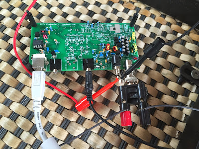
The mixer is working fine, and already has got two PT2399 circuits for delay. But now it is time to add some reverb. For reverb I decided to use an FV-1 based design. Experimental Noize has some nice small boards built around this chip, preprogrammed for different purposes. I decided to go for the SKRM-C8-R02 Mono-In/Stereo Out reverb and delay module.


I wanted to use a rotary switch to select between the different programs. The SKRM data sheet proposes to use a 74HC148 8 to 3 Line Priority Encoder for this purpose. Hence, there is a need for a small PCB to mount the SKRM and the 74HC148 (in addition to some additional components). Although I have used KiCad and OSH Park for PCB production previously, I wanted to test Fritzing for this small project.


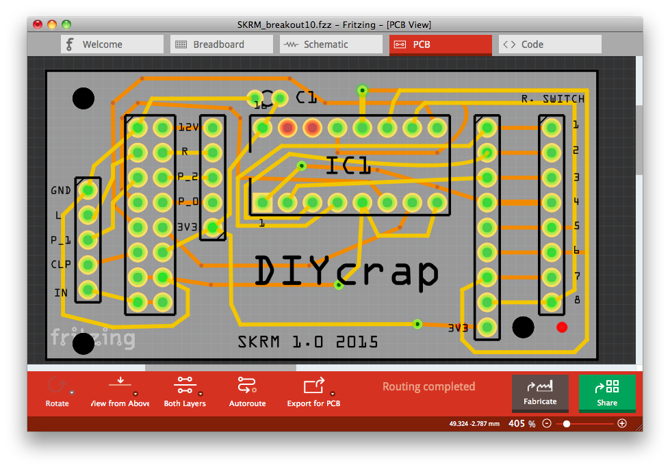
I drew a quick diagram in Fritzing, swithced to PCB-view and the auto-router took care of the rest (at least most of it).


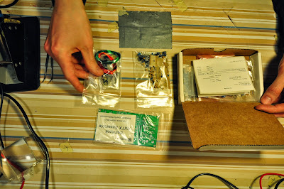
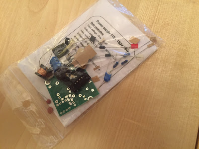
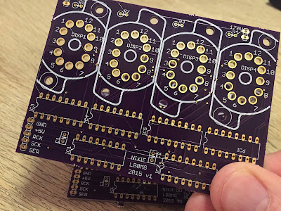
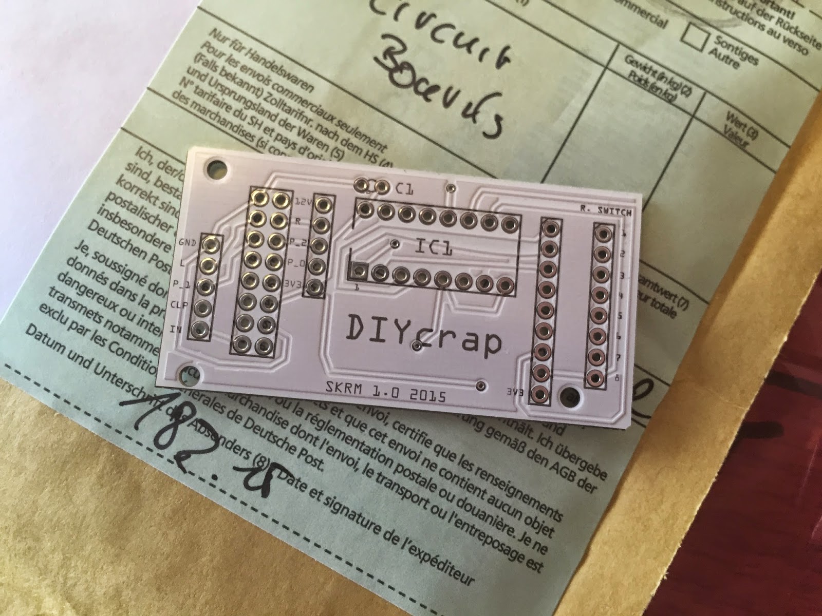
After a about ten days the card arrived in my mailbox.


The board came out quite nicely. Although I am very satisfied with the result, I do not think I will use Fritzing for my next project. OSH Park and other alternatives are way cheaper, and I think the Fritzing software is a bit limited compared to Eagle or KiCad (and even if the Fritzing-software is very simple to use, Eagle and KiCad are not that difficult to learn). The files are available at the Fritzing-site in case you are interested.


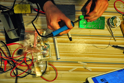
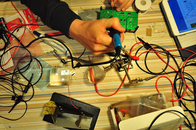
It took about 10 minutes to add the few components :-). It is only a 74HC148, a capacitor and a pull up resistor network.


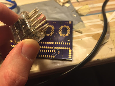
Then I slammed the SKRM on top of it, soldered the connectors, and started jamming with some heavy reverb. But wait, I forgot one thing, namely to securely mount the PCB inside the mixer. A simple solution is to screw standoffs to the front panel, but the screws would interfere with the front panel design. I could also glue the standoffs to the front panel, but I just hate to glue things together when there is a slight chance that I might want to dismantle it later.


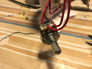
Hence, I created a plate to screw the PCB standoffs to, that is fastened with the rotary switch. It is designed in OpenSCAD and 3D-printed.


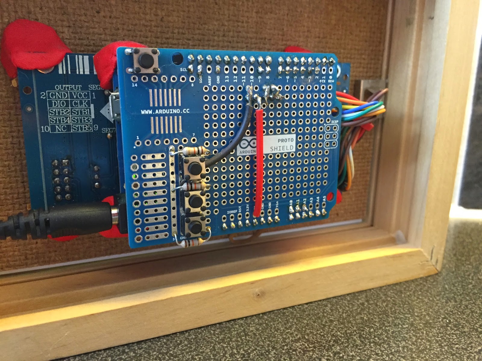
The above picture show how it looks like inside the mixer. Notice that the plate (in pink) is fastened together with the rotary switch.


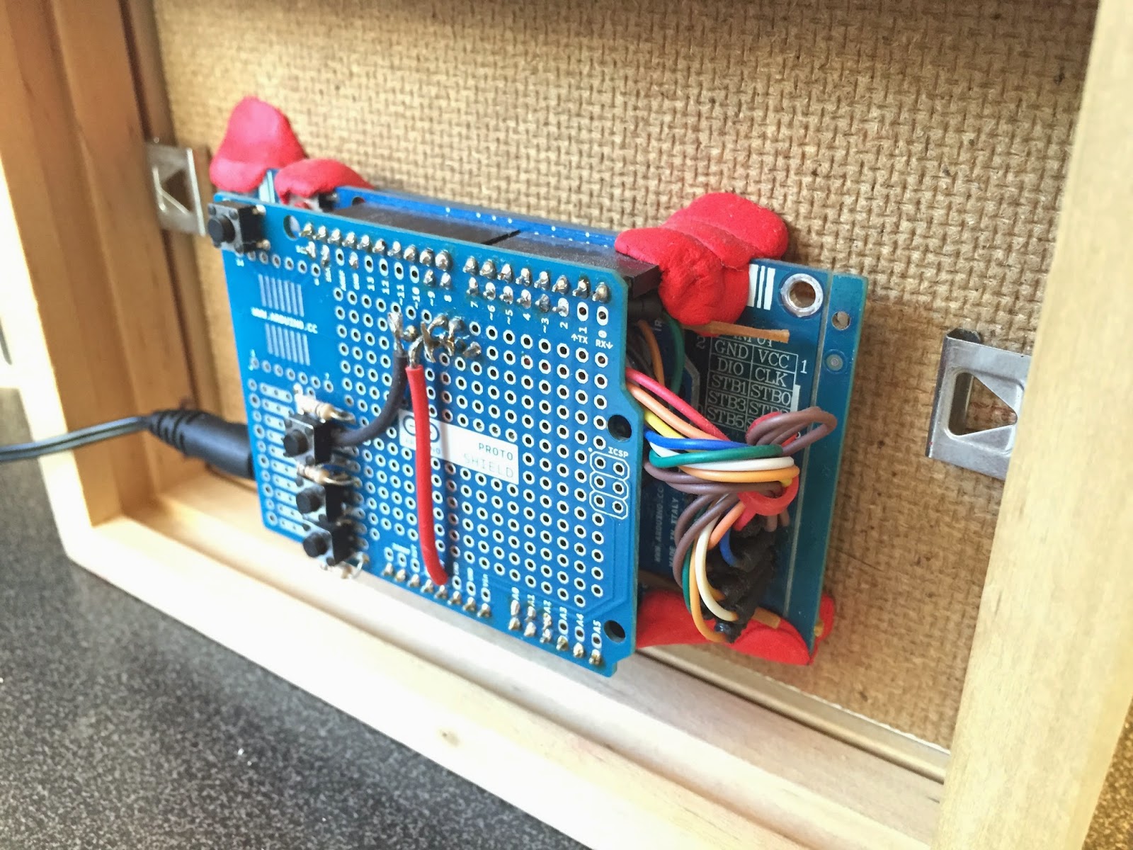
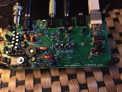
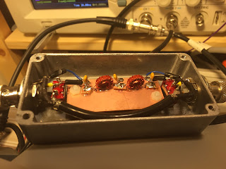
The above picture show how the mixer looks like inside. The SKRM is driven by a LM7805 which is connected to the +12V rail (the blue heatsink can be seen on the bottom part of the picture). The circuit draws about 170mA, even if the data sheet states it should be less than 75mA. The reason? I do not know.


DIYcrap mixer. Now with reverb.


Receiving JT65 with RTL-SDR

$
0
0
A couple of weeks ago I bought a RTL-SDR (software defined radio receiver) dongle with the 820T2 tuner chip. You just cant beat the fun/price ratio on this one. For 11$ (with free shipping) it is a bargain, and it is a great way to learn about radios (at least the reception part).

A bargain on AliExpress

Initially I used Gqrx on my Mac to communicate with the RTL-SDR, but eventually I had to resort to SDR# on Windows 7, as it has a bit more features. I have the impression that most radio (and ham-stuff) is made for Windows rather than Mac or Linux.


Apparently not much activity on 10m, but JT65 lurks there in the noise
Even with the standard antenna I had no problem receiving FM broadcast between 88-108 MHz, DAB around 200 MHz, some public transport transmitting FM on 151 MHz and some sporadic narrow FM around 140 MHz. I could also see that there was a lot of activity on 434 MHz and 868MHz bands from car keys, weather transmitters, baby calls and so on.

A few JT65 signals in the WSJT-X waterfall
However, what I really wanted to receive was amateur radio digital modes JT65 and PSK31 on the HF bands (preferably on 10m and 20m). I made a half-wave dipole for the 10m band (28MHz), and soldered the coax directly on the board. The RTL-SDR seem very noisy on HF and all I got initially was a weak RTTY signal on 10 m (which I was unable to decode), and a brief SSB-reception. I guess that one reason for the bad performance is that the strong FM broadcast signals on 88-108MHz interferes with the lower frequency bands.

Receiving JT65 in WSJT-X

However, after a bit of tweaking with the audio levels in SDR# and WSJT-X, I was able to receive some JT65 messages. It was incredibly fun to receive signals from Spain, Russia, South Africa and Brazil (among others) on this 11$ stick and my home-made dipole antenna. (Now I finally understand what the amateur radio people are so intrigued about.)

Received JT65 on 10 m from ZS6KMD in South Africa (9715km)
JT65 on 10m from PY2RED in Brazil (10550km)

Obviously, there are some improvements that can be done with the RTL-SDR to help HF reception. A FM-broadcast bandpass filter would eliminate the interference from the strong FM broadcast transmiters. As I am mainly interested in HF, and do not care about the performance above 30MHz, a simple low-pass filter at 30MHz will probably also do the trick.  Better shielding and filtering on USB can also help. Many folks are also using an upconverter, for example the Ham-it-up, which is undoubtedly the way to go to improve HF sensitivity.

Although I might try to improve HF reception on the RTL-SDR later, I will rather go building a Softrock RXTX SDR Tranceiver. The said kit is already on my workbench, and the soldering iron is hot. More to come...

Script for downloading all Popular Electronics magazines

$
0
0
The great page http://www.americanradiohistory.com/ has got loads and loads of old radio and electronics magaizines for download. Among these are venerable Popular Electronics magazine spanning from October 1954 to October 1982. It is really great to read all these old magazines, not only for historic reasons and for fun, but there are lots of electronic circuits, loadspeaker designs, and more that you can build as is or use for inspiration for new projects.


Probably the most famous issue is the January 1975 issue presenting the Altair 8800 computer kit. Now you can build your own based on the original instructions :-)

Inspired by Peter B. Mark, which has published a script that downloads all 73 ham radio magazines from arxive.org (highly recommended magazines), I made the following python script. The script downloads the entire series of Popular Electronic magazines. Now I can read through all the editions on my iPad even when I am offline, for example when I am waiting for my flight on an airport with nothing else to do and no WiFi.

Disclaimer: The whole bunch of magazines will occupy about 3.5GB of disk space. Furthermore, the naming of the directories on americanradiohistory is not concise, so the script might seem a bit crappy. But it works! If you exit the script while it runs, it will not download previously downloaded magazines when you restart. Good luck.

#!/usr/bin/python
"""
Download pdfs of Popular Electronics Magazine

"""
import os
import urllib2
import urllib

START_YEAR = 1954
END_YEAR = 1982
OUTPUT_DIR = "PopularElectronics"

MISSING = ('PopularElectronics/Pop-1954-01.pdf', 'PopularElectronics/Pop-1954-02.pdf', 'PopularElectronics/Pop-1954-03.pdf', 'PopularElectronics/Pop-1954-04.pdf', 'PopularElectronics/Pop-1954-05.pdf', 'PopularElectronics/Pop-1954-06.pdf', 'PopularElectronics/Pop-1954-07.pdf', 'PopularElectronics/Pop-1954-08.pdf', 'PopularElectronics/Pop-1954-09.pdf')


def main():
    if not os.path.exists(OUTPUT_DIR):
        os.mkdir(OUTPUT_DIR)
    downloadPopMag("Pop")
    downloadPopMag("Poptronics")

def downloadPopMag(prefix):
    for year in range(START_YEAR, END_YEAR + 1):
        for month in range(1,13):
            fileName = "%s/Pop-%d-%02d.pdf" % (OUTPUT_DIR, year, month)
            if not os.path.exists(fileName) and fileName not in MISSING:
urlyear = year - 1900
tenyear = urlyear - (urlyear % 10)
strtenyear = str(tenyear) + "s"               
if(urlyear > 69):
urlyear = year

editionString = "%s-%d-%02d" % (prefix, year, month)

url = "http://www.americanradiohistory.com/Archive-Poptronics/%s/%d/%s.pdf" % (strtenyear, urlyear, editionString)
                print("Downloading: %s..." % url)
                print("To: %s" % fileName)
                try: pdfData = urllib2.urlopen(url).read()
except urllib2.HTTPError as e:
# Probably wrong prefix. Try with the other prefix later
print e.code
else:
                outFile = open(fileName, "wb")
                outFile.write(pdfData)
                outFile.close()
            else:
                print("Skipping: %s" % fileName)


if __name__ == "__main__":
    main()


10 Great Audio Books for Makers and Geeks

$
0
0
Disclaimer: The DIYcrap blog is meant to be exclusively about crap that I am making. This post is going to be one rare exception to that rule.

I am a sucker for inspirational and geeky audio books. Although there are tons of excellent non-ficion books on paper or as e-books, not all of them are that good when transferred to audio. Some audiobooks are, however, really good and can make a boring commute become the most inspirational time of your day. This is a non-prioritized list of some of the best audio books about making, geeking, nerding (whatever) that I have heard during the last two years.  They are all positive, refreshing and inspirational, and explains why new inventions in technology make the world progress towards a better place. These books are perfect if you are fed up with all the negative news stories telling you the world is going to hell and that we are soon going to die from the melting polar ice, hunger or terrorism.

Enough said. Lets begin with the list, emphasizing again that the list is not prioritized.

1: The Second Machine Age: 

Work, Progress, and Prosperity in a Time of Brilliant Technologies


Written by: Erik BrynjolfssonAndrew McAfee
Length: 8 hrs and 49 mins
Published:2014

The book explains how digital technology dictates changes in the economy. The authors give many examples on different technologies that contributes to this change, such as robotics, 3D-printing, artificial intelligence and autonomous vehicles. The thesis of the book is very good, but on the negative side, the book is very similar to "The race against the machine" written by the same authors. If you have read (or listened) to the previous book, you can skip this. If you have not read the first book, you should choose "The second Machine age" as it is more updated.


2: Stuff Matters: 

Exploring the Marvelous Materials That Shape Our Man-Made World


Written by:Mark Miodownik
Length:6 hrs and 34 mins
Published:2014

This book is all about materials science. The author goes into detail about the history behind some key materials and the impact they have in our everyday lifes. Materials such as glass, steel, plastic and chocolate are explained with lots of humour and with interesting stories. If you have forgotten absolutely everything from your chemistry classes this book can reboot your interest in that direction. 


3: The Innovators: 

How a Group of Hackers, Geniuses, and Geeks Created the Digital Revolution


Written by:Walter Isaacson
Length:17 hrs and 28 mins
Published: 2014

This book describes the fascinating history of the computer and electronics age. Among the heroes whose lifes and work are described are Ada Lovelace, Charles Babbage, Grace Hopper, Howard Aiken, Steve Wozniak, Steve Jobs and Bill Gates. It is obvious already in the first pages that Walter Isaacson does not like the romantic illusion of a lone inventor often described in biographies. He rather advocates that collaboration between different people is the main driver behind innovation. Overall, the book is really great, it is well written, and it goes through the whole history of information technology.


4: iWoz: 

How I Invented the Personal Computer and Had Fun Along the Way


Written by:Steve Wozniak, Gina Smith
Length:9 hrs and 12 mins
Published: 2007

The books is told by Steve Wozniak about Steve Wozniak. In fact, the whole book is about Wozniak. Wozniak, Wozniak, Wozniak. As you probably can tell, there is a lot of bragging self-centered Wozniak in there, but who cares? Wozniak is an electronic genius, and he knows it. Although the book is badly edited, there are lots of interesting stories in here.

Walter Isaacson claims in Innovators (above) that Steve Jobs and Steve Wozniak were equally important in making Apple a big success. It might be true from a business point of view, but Wozniaks romantic story of creating a working computer sitting on his own is of no doubt the more interesting story of the two (at least from a geeky point of view).


5: Abundance: 

The Future Is Better Than You Think


Length:10 hrs and 22 mins
Published:2012

This book advocates that mankind could not only be causing all problems we face on earth, but we can also do something about these problems. Thanks to recent developments within digital technology, material technology and so on, we can actually improve the life of all people with water purification, diagnostic apps, new means of food production, renewable energy etc. If you are tired of all negative news stories telling you the earth is going to hell, this book will bring the optimist out in you.


6: The Long Tail: 

Why the Future of Business Is Selling Less of More


Written by:Chris Anderson
Length:8 hrs and 1 min
Published: 2006

This book is already a classic. You can read more about Chris Andersons concept on his web-page, and he explains it like this: "The theory of the Long Tail is that our culture and economy is increasingly shifting away from a focus on a relatively small number of "hits" (mainstream products and markets) at the head of the demand curve and toward a huge number of niches in the tail."

Most of Chris Andersons predictions in this book has already come true, and it might seem somewhat outdated. However, the main thesis still holds, and it is well written, and highly recommended.


7: Automate This: 

How Algorithms Came to Rule Our World


Written by:Christopher Steiner
Length: 7 hrs and 41 mins 
Published: 2012

Although the statement that algorithms "came to rule our world" is very exaggerated, the book has some interesting stories. Most of the use of algorithms described in the book is from Wall street, and there is no doubt that algorithmic trading has changed the way Wall street and that part of the economy is working (or not working). I would not use this book to teach people about algorithms. Novices might even be scared to believe that algorithms are, in fact, taking over the world. But as pure entertainment, this book is recommended.


8: Makers: 

The New Industrial Revolution


    Another book of Chris Anderson made it on my list! This book is about how 3D-printers, laser cutters, digital fabrication, Kickstarter, Arduino and the new DIY/Maker-movement is altering how businesses are created and run, and how the digital age also influences the production of physical stuff (i.e., bits and atoms). 

    Anderson believes that we face a new industrial revolution, and that the new tools and production processes can offer a way for USA and Europe to incource production of physical objects from China. He might or might not be true about this thesis. It does not matter for me. The book is full of optimism about the future and it just makes me want to make stuff right away.


    9: What If?: 
    Serious Scientific Answers to Absurd Hypothetical Questions


Written by:Randall Munroe
Length:6 hrs and 36 mins
Published: 2014

This book is full of humor and hard facts. It provides answers to questions like "What is the farthest one human being has ever been from every other living person? Were they lonely?", and "What if you tried to hit a baseball pitched at 90 percent the speed of light?", or  "How fast can you hit a speed bump while driving and live?" and " If there was a robot apocalypse, how long would humanity last?". If you have ever read (and understood) Randall Munroe’s iconic webcomic xkcd.com, this book is for you. The book makes you proud that you enjoyed physics and chemistry classes all those years ago while the other kids hated them.


10: Bold: 

How to Go Big, Make Bank, and Better the World


Written by:Peter H. Diamandis, Steven Kotler
Length: 9 hrs and 6 mins 
Published: 2015

This book is written by the same authors that wrote Abundance in 2012. It is sort of an update of this book and sort of isn't. It is mainly a motivational book for business people wanting to understand exponential technology. For an inventor or engineer, it can be quite irritating reading a book that constantly talks about going big, bold and make a billion-dollar company.  Unfortunately, most of the stories and examples in the book are well-known and does not bring anything new to the table.

The book is narrated by one of the authors, Steven Kotler. A very bad idea. Although the book is very optimistic in its style, the narration seems very monotone, negative and depressive. It is as if he is just about to jump off a cliff. Why am I even bothering to recommend this book? Well, it is about creating businesses that changes the the world, it is optimistic, and makes me want to be an entrepreneur.


Pregnancy countdown device with Arduino

$
0
0
Once you or your spouse gets pregnant, thats all that matters in life. You immediately starts to count down to due date and you constantly want to know the current weight and length of the baby. And trust me; you do not wish to use a freakin iPhone app for that. You (and your baby) deserve a dedicated device for the job!

This is what you are waiting for

I hereby present my pregnancy countdown device. I built this a couple of years ago, and the baby whose due date was steadily counted down with this one is now a walking and babbling toddler. This is a simple weekend project that you can assemble with junk-box parts and an IKEA picture frame.


2 days and 22h to due date. You better pack the bag!


You are in week 40 and the baby is now 51.5 cm!


You are in week 40 and the baby is 3558 grams.


The device switches between due date countdown, baby length, baby weight and the current time (above) with 5 seconds on each.


The device is based on a Arduino UNO R3, a DS1302 real time clock and a 8-digit 7-segment display. The DS1302, and four buttons are soldered on a prototyping shield. The Arduino and the display are "glued" to the IKEA picture frame with sugru. I used an exacto knife to cut a hole in a 10x15cm picture and used an old 35mm film strip as a bezel for the 7 segment display diodes.

The buttons were initially for setting the due date, but I did not care to implement that in the software. Hardcoding is sufficient for this purpose (depending on how many kids you are planning of course).

The core of the code is basically to calculate the length and the weight of the baby given a specified due date. For any day the weight and the length can be interpolated from the tables below (showing weeks). The length (in cm) and weight (in grams) are average values for northern european babies. If all your meals are pure butter and coke during pregnancy (it can happen), you mileage may vary.

double lengthTable[] = {0,
0,
0,
0,
0,
0,
0,
0,
1.6,
2.3,
3.1,
4.1,
5.4,
7.4,
8.7,
10.1,
11.6,
13,
14.2,
15.3,
16.4,
26.7,
27.8,
28.9,
30,
34.6,
35.6,
36.6,
37.6,
39.9,
41.1,
42.4,
43.7,
45,
46.2,
47.4,
48.6,
49.8,
50.7,
51.2,
51.7,
51.5,
51.3};

int weightTable[] = {0,
0,
0,
0,
0,
0,
0,
0,
1,
2,
4,
7,
14,
23,
43,
70,
100,
140,
190,
240,
300,
360,
430,
501,
600,
660,
760,
875,
1005,
1153,
1319,
1502,
1702,
1918,
2146,
2383,
2622,
2859,
3083,
3288,
3462,
3597,
3685,
3717,
3717,
3717,
3717};

Motion sensor to detect sneaking toddler

$
0
0
Once the kids are asleep at night, you can finally relax. Aahh. Maybe you want to stress down with a violent splatter movie with the volume at 11? In this situation you definitely do not want the kids to sneak around in the house behind you and watch the movie in secrecy. In that case you will have a lot of explanation to do. (Dad? What happened to the man's brain?). Or maybe you and your spouse are in your bedroom making new kids..? You definitely do not want the existing kids to interrupt such a beautiful moment. And difficult questions could possibly be asked.

The trick is to use a motion sensor outside the toddlers bedroom and a portable doorbell with visual and audible alarm. All possible crisis is henceforth avoided.


I bought one of these Nexa doorbells, and a...


... Nexa IR detector.

The problem with the doorbell is that is also chimes when someone are walking around in the house during daytime. It also chimes to loud for the intended purpose. Therefore, I added a volume control, that also serves the purpose as a on/off switch.


The doorbell is a simple design built around a 433MHz receiver


A 100k audio pot for the junk box does the job. I also tried with some resistors to limit the 100k pot with mixed success. It does not matter much for this purpose.


I drilled a hole in the front panel, and ...


Voila. A doorbell with a nice blue LED and fully adjustable volume with a Moog style knob. I glued some eyes to the doorbell to make it seem a bit more friendly.

OpenPanTilt electronics

$
0
0
It has been a while since I made the OpenPanTilt prototype. It is now available on Thingiverse:655790 and I am quite surprised about the feedback and attention it has gotten. Billions of people have now downloaded the design files (at least 430) and millions have asked me about the electronics (at least three individuals). It is about time that I provide some details. (I also plan to publish a few more time lapse videos to show this magnificent piece of equipment in action.)


The electronics consist of an Atmel ATMega328P-PU a.k.a barebones Arduino. The AVR is run on 16MHz and driven by 5V from a 7805 regulator. It can be bootloaded using something like this. Two optocouplers drives the camera (shutter and focus). I guess any optocoupler will do, but I used 4N35. Besides from a reset switch and some filtering caps here and there, thats it.

The stepper motors are driven by easydriver stepper motor drivers. I made room for three of these on the board, so it can drive a camera dolly in addition to pan and tilt.

The schematics was created in Kicad. This was my first project in Kicad, and since I was impatient, I used the autorouter in Kicad according to the instructions at Wayne and Layne.  I think the autorouter performed well for this small project.

When the board seemed fine, I created the gerber files using this guide at Toymaker Television. Notice the "mirror X-axis" when creating the drill file. Finally, I submitted the gerbers to OSH-park. The project can be found at OSH-park if you are interested.


The PCBs have excellent quality and the soldering goes like a blast.


Two Easydriver stepper motor drivers are fitted on the PCB (room for one more).


The user interface is simply a TM1638-based 8x7segment display with control buttons. It was ordered from China and can be found everywhere on the interweb. I soldered some wires going from the TM1638 PCB to my own panel mounted control buttons.


In the above picture you can see the extremely simple user interface. It works as follows:
  1. Use the buttons to pan and tilt the head to the desired start position.
  2. Press P1 (programs the start position).
  3. Use the buttons to pan and tilt the head to the desired end position.
  4. Press P2 (programs the end position).
  5. Press Start. The Pan/Tilt head will now return to the start position and will start shooting.
You can optionally press the Menu button before programming to set the interval between each step and each picture.
    This is extremely easy, but it works. The display shows the number of pictures shoot and the current pan/tilt position. I choose to use a 7-segment display just because I like the old school looks of it. A 20x04 LCD with a rotary encoder would, of course, be more sensible.  


    The box has connectors for 12V DC, camera (shutter and focus), Pan stepper motor, Tilt stepper motor and an auxiliary stepper motor.

    Some mistakes 


    I did some mistakes while building the control unit. If you want to build something similar, you should try to avoid these.

    First of all, the 12V power header for the stepper drivers was was reversed on my PCB layout, meaning that the driver did not initially get any power.


    Hence, I had to modify the mounting of the easydrivers a bit (notice the white wire on the above picture). No big deal, but it means that you should not order these boards from OSH-park, even if the board was selected amongst the staff picks of the week. :-)

    A second error on the board is that there is no protection whatsoever on the 12V DC. No diode, no polyfuse, no fuse. Nothing. At least a diode should be placed in there, somewhere.

    A third thing that I was not aware of is that the easydriver board must be connected to a load. Without a load (i.e., a stepper motor), the driver IC will burn up. Totally stupid, but I burned up two boards this way, and had to wait forever to get some new boards from Shenzhen, China. Thankfully, they are easy to replace.

    Summary


    Ok. Thats it. I learned a lot while building OpenPanTilt. And, best of it all, it works. If you want to build something similar, or have comments, please let me know. I know Josh Sheldon was inspired by OpenPanTilt and has developed some of the ideas further, and I must say, with impressive results.


    Building a SoftRock Ensemble RXTX SDR

    $
    0
    0

    Introduction


    The last couple of months I have been listening a lot to the soldersmoke podcast. In case you do not know, it is two guys, Bill N2CQR and Pete N6QW babbling about building homebrew radios. I am very happy I found this podcast. It is highly inspiring, and by listening to the two experienced homebrewers I immediately wanted to melt some solder and build radios myself. Hence, I had to get myself a licence (got it last week: LB0MG) and start soldering radios.

    As much as  I would like to be in the possession of a totally homebrew fundamentalist discrete component ham radio station (like Bill N2CQR), I concluded that I rather should start out with a kit. (I guess some homebrew fundamentalists threw up a bit now since I mentioned the word "kit").

    Building the Softrock RXTX


    Anyway, choosing a kit I might as well do it the modern way and build a SDR. I initially considered the PeaBerry SDR, but ended up with the Softrock Ensemble RXTX SDR Transceiver kit since I have the required sound card capabilities laying around after my previous synth projects.


    The kit is nicely packaged and contains about 250 parts. Some through hole and some SMT.
    I am pretty sure I will not do much contesting in any perceivable future so I choose to build the Softrock for the 17m, 20m, and 30m bands (two contest free bands).

    There is an excellent build manual on the pages of WB5RVZ.  I addition I have had great use of some of the videos from W2AEW to understand the concepts of SDRs and to improve my toroid winding technique. He has some of the best engineering videos on the entire Youtube.


    Progress


    So far I have built the entire RX part of the kit and it has come along quite nicely. The SMT parts are rather easy to solder. Surprisingly enough, the through hole parts are a bit more challenging since there are very little space around the components, and the pads are really small and not gold plated. A lot of flux really helps.


    The only mistake I did was that i lost the LT6231 SMT RX opamp (probably in the vacuum cleaner). Straight away I ordered two new chips from DigiKey and when they arrived at my door merely 36 hours later, I was so eager to get the RX working, that I accidentally soldered the small SMT chip in the wrong orientation. Hence I had to use the second one (glad I ordered two of them). But it worked! I got a small Image rejection problem, but traced it down to a setting in the sound card I used (Behringer UCA-202).


    In the above picture you can notice the excellent indoor dipole "antenna" connected to the Softrock. The length of the dipole is about 5m, so It is not the best choice for receiving either of the bands. I guess some you antenna fundamentalists threw up watching this picture, but hey, the antenna sort of works. 


    To please the homebrew fundamentalists out there, I used my 22 year old homebrew LM317 bench power supply to provide clean and pure 12V DC.


    I connected the receiver to HDSDR, grabbing the I/Q signals. I have received SSB, RTTY, WSPR and JT65 on 17, 20, 30 and 40m bands. In the above picture you can see some digital signals popping in at 20m. I tried to use WSPR software directly on the I/Q signals from the radio but with little success. I had to output USB audio from HDSDR via a second sound card and then into WSPR.


    From my perspective the RX test was a great success. Even with the indoor "antenna" I received WSPR on 30m from 60 different transmitters over a 24h period, and even across the pond. You might see LB0MG in the above map: Yeah, that's my Softrock sniffing RF from the ether, placed in an attic in Norway. 

    I even got reports coming in from K1JT (yes, the Nobel laureate, Joe Taylor, that created WSPR) himself and got a bit starstruck. It is funny to think about the fact that he was transmitting his modest 5 Watts from New Jersey, and that my home soldered Softrock received his RF vibrations all 6000km away, even with a crappy piece of wire as antenna. The radio gods are undoubtedly on my side on this one.  

    Now, I am eager to generate some RF myself and will get on finishing the TX part.


    Softrock RXTX completed

    $
    0
    0
    After finishing up the receiver part of my Softrock Ensemble RXTX SDR transceiver with great success, I got really motivated to get the transmitter going. The last weeks I have followed AB4UG's progress building his own RXTX with great interest, and I got even more motivated to finish my own kit when I saw that he got the last component soldered on his RXTX.

    Soldering the last component on the RXTX

    Building the TX part was fairly easy after having built the RX part. The first thing after melting the last piece of solder on the board was to make a 50 ohm dummy load using a few resistors, and then to measure the output power with my scope. After that, I balanced the I/Q signals by playing with the TX image rejection settings in WSPR and by watching the transmitted signal on a RTL-SDR receiver. The RTL-SDR operated in a software direct sampling mode to make it work on the 20m band. This setup is not the best tool for this calibration task, but I think I came pretty close in my effort. I might check it up more thoroughly use a spectrum analyzer later.

    RXTX is running WSPR

    WSPR is an excellent choice for testing out a freshly built transceiver since it gives immediate feedback through Internet if anyone out there receives my signals. After a bit of fiddling, I got the RX mode running directly on I/Q in WSPR, and prayed to the radio gods that the TX would work as well. After verifying that the transmitter did "something" when connected to WSPR (it went hot), I left the softrock running for 24h with about 1W output. Then I just hoped that the black suited government frequency authorities would not kick down my door to revoke my amateur licence due to RF harmonics or for causing QRM on the image frequency.

    Both RX and TX is now working in I/Q mode
    Luckily the frequency authorities have not been kicking down my door (yet). On the contrary, during one night of operation I have gotten WSPR reports that my signals have reached most of Europe and even across the pond to America!

    I can enjoy my working transceiver from my iPhone
    I am truly amazed that my 1W transmitter (which I bravely soldered myself) can reach more than 7000 km. Notice that my "antenna" is just an indoor wire dipole (at about 5m length).

    If you are listening on 20m and observe that my Softrock emits energy in the wrong parts of the frequency spectrum, please be kind to me. Please. I am a fresh amateur with very limited RF self esteem.

    Summary of the build experience


    I followed the excellent build guide of WB5RVZ step by step and it was really helpful. The most challenging part of the build was in fact soldering the through hole components on the awfully small soldering pads on the PCB. The SMT parts were mostly SOICs and 1205, which were easy. The Si570 (QFN) were the most challenging. I measured every resistor before soldering and took great care not to make any mistakes along the way. All in all, it was really an enjoyable build and the entire process building the transceiver took about 10-12 hours in total. The only mistake I did was to solder an opamp in the wrong orientation, but that was easy to fix.

    Future work


    The next step is to test out other WSJT digital modes such as JT65 and JT9 and to make some real QSOs. The goal is to make the Softrock operate stand alone on my Raspberry Pi2. 

    WSJT-X and HDSDR with Softrock RXTX

    $
    0
    0

    Introduction - A Raspberry failure


    My first (and, as it turns out, rather ambitious) plan was to use a Raspberry Pi 2 as SDR computer for my SoftRock, with Quisk, Fldigi and WSJT-X. The plan was to use VNC to connect to the Raspberry, so I could operate digital modes from all my devices; iPad, iPhone, Mac and so on.

    I made all of the above almost work. Quisk was easy to get going, but I struggled to compile WSJT-X. However, after a very time consuming upgrade from Wheezy to Jesse, I managed to make it run. But due to a conflict between Qt (the GUI framework in WSJT-X) and TightVNC, I could not make it run without a display connected. Bummer.

    Second bummer: I had a hard time getting my Behringer UCA-202 sound card work correctly,  It seems like that the left channel is delayed by exactly one sample relative the right channel on this card. Reading this, I gave up, and ended up purchasing a Asus Xonar U7. I made the Asus work with the Softrock RXTX, but only on 192KHz, which seemed to be to CPU intensive for the Raspberry. The sound quality was really poor. 

    All in all, I gave up on the Raspberry (for now), as I was eager to get the Softrock on the air and make some QSOs.


    Softrock RXTX and Asus Xonar U7 in a "Pelicase". Plenty of room for Power supply, LP-filter and SWR meter.

    Going all in for Windows


    Being a Mac and Linux user for many years, I finally took the plunge and purchased a Windows 7 based Lenovo machine. It was a bit painful, but I came over it.

    I now use HDSDR as the SDR program communicating with the Softrock RXTX with I/Q using the Asus Zonar U7. I use 48KHz 24bit at the moment (both directions) although the Asus can go all the way to 192KHz. I do not see the wide spectrum given by 192KHz being all that necessary for digimodes, but is certainly very handy to view the band in a glance panadapter-vise if you are searching for SSB ragchewers or whatever.

    To connect HDSDR to digital-mode programs I purchased "Virtual Audio Cable". It was dead simple to set up, and worked with WSJT-X straight away. I also use com0com as a virtual serial port to let WSJT-X enable TX-mode on the Softrock through HDSDR. I have not made full CAT-control working yet, so I have to dial the tuning frequency on both WSJT-X and HDSDR.

    I do not know anything about logging QSOs online or shipping QSL cards, but it has came to my understanding that logging as such is important and after a quick search I installed DXKeeper. It is free and it seems to work.

    DXKeeper interoperates seamlessly with JTAlert which is a must-have add-on for WSJT-X.

    To make all the above interoperate, the applications have to be started in the correct order. Virtual Audio Cable and com0com seems to always work, and can be set and forget. To make HDSDR, WSJT-X, JTAlert and DXKeeper play nicely, I created a small script:

    echo off
    echo "Starting ham radio software"
    echo "Starting DXKeeper"
    start C:\DXLab\DXKeeper\DXKeeper.exe
    timeout 20

    echo "Starting HDSDR"
    start """C:\Program Files (x86)\HDSDR\HDSDR.exe"
    timeout 10

    echo "Starting WSJT-X"
    start C:\WSJT\wsjtx\bin\wsjtx.exe
    timeout 15

    echo "Starting JTAlertX"
    "C:\Program Files (x86)\HamApps\JTAlert\JTAlert.exe" /wsjtx

    I saved it as a *.bat on my desktop. By clicking the bat-file the applications starts in the correct order, and ensures that JTAlert can talk to the DXKeeper database.

    HDSDR, WSJT-X and JTAlert. The radio was absent when the picture was taken.

    First QSO


    With all the above running on my fresh Windows computer I threw out a simple dipole antenna and tried to make some QSOs with JT9 and JT65. M0LMI, Lubomir, from England, answered one the very first CQs sent by my Softrock and minutes later I had made my first QSO! I checked the power with my scope later and it turns out I was only running about 0.5 Watts. After cranking up the power to 1 Watt I made a few more QSOs, and I have to say I am happy with the setup. I have only been running on 20m so far.

    JT9 and JT65 may be an easy mode compared to CW, but with limited power and a compromise antenna (I have no idea about the SWR and resonance and all that), you sure have to be patient.

    Future work


    I still have not given up on Raspberry Pi2, but before working on that, I will build a low-pass filter so I can operate on 30m. I think I also need a decent power meter so I can have an idea on what is going on. It is probably going to be a power meter DIYcrap style.


    Upload log files to QRZ.com automatically using LogPusher

    $
    0
    0

    Introduction


    Many radio amateurs upload their QSO logs to QRZ.com. Not all logging programs can interface with the QRZ API, and unless you are a subscriber, the API does not work. The log can be uploaded manually, but this is a tedious process.

    Hence, inspired by the bash-script by WB4IT I have written a simple C# program (LogPusher) that takes care of the business. All there is to it, is to enter some settings in the dialog: Mainly your user name, password and log book id at  QRZ.com, and point to the choosen log file. As soon as the file changes, it will upload to QRZ.com automatically.

    LogPusher


    Enter the settings for your QRZ.com account


    Make some contacts and wait for LogPusher to upload the new log tile

    LogPusher works by first logging in to the front page of QRZ.com and by keeping the session cookie and after that it enters the logbook and uploads the file. It seems simple, but I had to monitor the messages going between Google Chrome and QRZ during manual uploading several times until I got it right. I used Fiddler for this, and it was excellent.

    I had great help from this page on stackoverflow discussing how to upload HTTP form entries from C#.

    How to get it?


    LogPusher is available at Github: https://github.com/DIYcrap/LogPusher/. You may download the code (press download zip at Github) and compile it with Visual Studio 2015 (it is free) and modify it yourself, or you can just use the executable file directly.

    Please let me know in the commentary field below if you like the project or if you encounter any issues or if you have any suggestions for improvements. Stay tuned for updates on this project.


    Lowpass filter for 30m

    $
    0
    0
    I just finished a 30m lowpass filter for the Softrock Ensemble RXTX tranceiver.


    I used the schematic provided by WB5RVZ


    L200 and L201 is wound to about 0.9uH, whereas C200 and C202 is 100pF and C201 is 330pF. Everything is soldered to a PCB (ugly construction) and I added two switches and a coax to enable on and off switching of the filter.


    Ugly construction...


    I tested the filter using a 25 MHz function generator and my Rigol 1052 scope. The filter was connected to a dummy load. The first two pictures below show 1 Vptp at 10 MHz with the filter off and on respectively. The two pictures thereafter show 1 Vptp at 20 MHz (on and off).

    10MHz lowpass filter switched off

    10MHz lowpass filter switched on

    20MHz lowpass filter switched off

    20MHz lowpass filter switched on

    As a three pole filter it should have a roll off at 18db/octave. This seems about right when I compared 12 MHz and 24 MHz (9.3V and 0.9V ptp respectively). I measured the -3dB point to be around 14.7 MHz. The purpose of the filter is to reduce the the 2nd harmonic when transmitting in the 30m band (10.1 MHz). The second harmonic is down about 13dB.


    Function generator on burst mode, Oscilloscope on FFT, center frequency is 10.5MHz and filter is off

    Same as above, but lowpass filter is switched on

    I also looked at the FFT on the Rigol scope while using burst mode on the function generator. In the pictures above, the center frequency is 10.5MHz and the grid is 12.5MHz in the X axis and 10dB in the Y axis. Here it seems like the filter contributes to 20dB attenuation at 23MHz which is about right.  I have not measured the second harmonic while using the Softrock, since I have no real spectrum analyzer. However, as the filter is working, I guess I can legally transmit on 30m. 73!


    Homebrew dummy load

    $
    0
    0
    I have created a simple 50 Ω dummy load to test transmitters. I also added a simple RF diode detector so I can measure the peak voltage, and calculate the power.


    The dummy load consists of eight 100 Ω resistors rated at 2 W so the load should handle 16 W, at least for short periods. I constructed the dummy load using a combination of ugly construction and Manhattan style, by gluing pieces of PCB  (as isolation pads) on top of a ground plane PCB.  Then I soldered the components directly on the copper without drilling holes.


    RF Probe


    The RF probe part consist of a simple 1N4148 diode and a 0.01 uF ceramic capacitor. I only had a 50 V capacitor in my junk box, but it should be sufficient given that this is a 16 W dummy load and 16 W translates to 40 V peak.

    I added female banana connectors, which connects to a multimeter. The power can be calculated by Ohms law by subtracting the forward voltage on the diode from the measured voltage, then multiply by 0.707 (to get RMS), then square the result and finally divide by 50 Ω. Some homebrewers add a voltage divider to their RF probes using a 4M7 resistor to get RMS voltage directly. I did not bother since I am sure the input impedances on my multimeters varies.

    The calculations might seem a bit cumbersome, but I might print out a small lookup table and glue it to the box to have some ballpark figures. However, this is not a precision instrument. The forward voltage on the diode varies with load and can be somewhere between 0.4 and 0.7 V. I simply use 0.5 V in my measurements.

    So far, the dummy load has been very convenient when testing my Softrock RXTX and its low pass filter,

    Further reading


    1. Jeelabs, Forward voltage drop on a diode
    2. NXP, 1N4148 data sheet
    3. N5ESE, Classic RF Probe

    Directional coupler

    $
    0
    0

    Introduction


    I have been struggling to understand how my simple dipole antenna works (or doesn't work). The diycrap way to understand stuff is usually to read, build and measure, and then read some more. The key factor here is the measuring part, as I need to measure the standing wave ratio (SWR) on the feed line, as this is a key parameter. To measure the SWR, I need a directional coupler. And it is going to be homebrew.

    Later, the coupler is going to be the basis of a SWR-meter, but for now, lets just look at the coupler.


    The directional coupler design is classic and well known. Notice the input port and the output port on the upper line and the forward port and the reflected port on the bottom line. (My graphics software is Field Notes.)

    Some theory


    The principle of the coupler is based on two toroid transformers. The first is a current transformer and the second a voltage transformer. Each taking samples of the signal on the main line. The two transformers are equal, reducing the current and the voltage to the same level, meaning that the impedance is constant. The two transformers are connected in such a way that for a forward signal, the signal cancels out on the reflected sample port, but adds up on the forward sample port. And vice versa, a reflected signal adds up on the reflected sample port but cancels on the forwards sample port. Since we now have a sample of both the forward signal and the reflected signal, it is straightforward to calculate the SWR.

    For a deeper understanding on how the coupler works, I recommend this web page, or the excellent YouTube video from W2AEW.

    Construction


    It is simple to construct the directional coupler. The transformers are FT50-43 toroid cores with 32 turns of 24 AWG enamel wire. The primary winding is simply a piece of RG58 through the torioid (i.e., one turn). Different designs use different toroids and number of turns. I settled down on a design found in Arduino projects for amateur radio.


    I used a aluminum box and BNC connectors. I used copper clad boards as shielding here and there. I did not have any 50 ohm resistors in my junk box so I used two 100 ohm resistors in parallel. They are all 2W resistors, which is totally unnecessary and overkill.

    Rudimentary testing


    Testing the forward port. The output port is connected to my 50 Ohm dummy load. As signal source I used my GW Instek GFG-8255 signal generator, which unfortunately maxes at 5.5 MHz. 


    8.2 Vpp on the input port resulted in about 244 mVpp on the forward port. Hence, the coupling factor is about -30dB. The signals are not in phase, but that does not matter for voltage measurements in a SWR-meter.


    Testing the reflected port


    8.2 Vpp on the input port results in 1.60 mVpp on the reflected port. This translates to a reflected signal of -74dB. The directivity is the reflected signal (-74dB) minus the coupling factor (-30dB) which equals -44dB.

    Testing over the HF band


    Later I borrowed a TTi TG2511 function generator which goes all the way up to 25 MHz. I tested with 10 Vpp on the input port and got these results:

    frequencycoupling factorreturn loss
    1.8 MHz-30 dB-84 dB
    3.5 MHz-30 dB-80 dB
    7 MHz-30 dB-75 dB
    10 MHz-30 dB-72 dB
    14 MHz-30 dB-69 dB
    18 MHz-30 dB-66 dB
    21 MHz-30 dB-65 dB
    25 MHz-30 dB-62 dB

    The directivity is between 54 dB and 32 dB. The numbers seem reasonable, but indicates that the coupler should not be used for VHF/UHF.

    Future work


    The plan is to build a power meter and SWR meter using AD8307 logarithmic amplifiers and an Arduino. I will probably base the device on the design from the book Arduino projects for amateur radio.

    Further reading


    Nixie tube experimentation with IN-12

    $
    0
    0

    Introduction


    I have always wanted to try out Nixie tubes in one of my projects, and here we go. Nixie tubes come in many different sizes and there are both top view and side view nixie tubes out there. I settled on some russian IN-12 top view nixie tubes as they are cheap, and should fit nicely on a front panel (for example on a radio).


    The IN-12 was originally used in russian multimeters, radios, frequency counters. This R-155A Brusnika Radio Station serves as a good example on how nixie tubes were used in the cold war era.

    Recently, this particular tube has been used for many hobby purposes such as clocks, geiger counters, etc. While I am mentioning it, the major page for steampunk and Nixie-fans is Bad dog designs having loads of excellent clocks using nixie tubes. Ok, enough drooling over other designs. Back to my modest attempts.

    Testing a nixie


    I purchased a 110-180V power supply kit from ebay. I highly recommend this kit from seller lumos-sk. It comes with an excellent build manual and was very easy to assemble.


    The assembled power supply was set to 170V...


    ...and the IN-12 glows fine.

    A PCB for four IN-12 tubes.


    To control the nixies, I made a PCB in Eagle. The circuit uses two 74HC595 shift registers to drive four K155ID1 decimal decoders.


    The schematic is shown above.


    It is possible to cascade several of these boards to drive eight, twelve, sixteen, etc Nixies from just three pins on the microcontroller. I ordered the PCBs from OSH-park, and they were excellent.


    However, I should have read Kevin Ryes blog before creating the PCB. I just took it for granted that the Eagle IN-12 part was correct, but as Kevin Rye found out, it is not. The pin numbering on the silk screen is wrong and the anode is connected to pin 5 instead of pin 1. However, if one ignores the numbering, my PCB works if the IN-12 is mounted on the back side of the board (i.e. mirrored). 


    Originally I planned to use IN-12 sockets (purchased from Ukraine) but since the IN-12 part was mirrored, the mounting holes were on the wrong locations and it made no sense to use the sockets. In addition, the parts I got were used, so I had to desolder chunks of 30 year old wiring. Totally boring work. So instead, I went back on Ebay and ordered some pins from the old Soviet Union (see picture above). They were excellent for this purpose.


    To test the shift registers, I copied the Arduino code made by Imperkins over at Instructables. The only change was to add support for an additional shift register.


    The above film shows the Nixie PCB in action.
    As mentioned, it is simple to cascade several PCBs to control more nixie tubes. My secret plan for the future is to use eight nixie tubes as a frequency display for a HF radio, such as Farhans Minima.

    Further Reading


    1. http://scott-bot.com/nixie-bot/
    2. KiCAD library
    3. IN-12 datasheet (in Russian)
    4. IN-12 geiger counter (with laser cutted parts).
    5. IN-12 clock (shares Eagle files and svg of front panel cutout)

    Homebrew SWR and power meter

    $
    0
    0
    First of all, this SWR meter in this article is not exactly homebrew, as I based the circuit on the schematic in the excellent book Arduino Projects of Amateur Radio. Although I bought the book and respect the copyright of the authors I will share my own schematic here. Why? First, the design in the book is not completely original and is based on similar designs from others. One example here.  Second, I changed a few things, removed some stuff,  and added some other things, to my own liking, so the design is not identical anymore.


    The circuit is based on two AD8307 log amplifiers, which are connected to the forward and reflected ports on a directional coupler.  The AD8307 amplifiers gives a DC voltage of about 25mV/dB of the input signal, which is amplified using an opamp (LM324). The opamp also provides the reference voltage to the Arduino (AREF) to ensure that the full ranges of the A/D converters are used.


    I used the fourth opamp in the quad LM324 to provide input voltage reading. That is why the PCB in the picture has two power jacks. One input and one output. That way I know the drive voltage for the radio. I primary plan to use this device for my Softrock.


    I created the schematic and the board in Eagle, and submitted the gerbers to Elecrow. I received 10 PCBs after about 25 days.


    The board is not much larger than a standard 20x4 LCD.


    I choose to use an Arduino nano rather than populating a AVR328 on the board and messing with USB converters. I am glad I did. I did one mistake on the board however. The Arduino was not powered from the 5V rail. The problem was that it was an error on the Eagle footprint for the Arduino Nano. I just downloaded the footprint file uncritically from the Internet without checking it. Other than that, It was fine.


    Another problem was that I got oscillations on the LM324 opamps connected to the AD8307. The oscillations were around 40KHz and about 400mVpp on top of the DC signal. Hence it was impossible to calibrate the device. The solution was to desolder the output capacitors on the LM324. I do not think they are really needed on a DC design.


    This was my first SMT design, and I am fairly happy with the result. The SWR and the power measurements seems accurate. I used the Arduino software from the book, and modified it to include a larger display and some other things. As you may notice, there are no buttons on the device. Originally I planned to use a rotary encoder and a bunch of menus, but as they say in the Soldersmoke podcast, menus are for restaurants. I totally agree. Besides, programming all kinds of features to the device is totally insane. This is a simple SWR meter and thats it. 

    Building Farhans Minima Tranceiver Part #1

    $
    0
    0

    Introduction


    I have started my most ambitious electronics project so far. After building my Softrock RXTX I was eager to learn more about RF designs, and HF radios in particular. I came across Farhan, VU2ESE, via Soldiersmoke and decided to build a tranceiver based on his Minima.

    There are three published versions, and many variations in between that are produced by others. All versions are based on a Si570 PLL Local oscillator and a discrete component BFO.


    The first version uses mostly discrete components, KISS-mixer and discrete component audio amplifier, The IF is 20 MHz and it switches between two filters to cover the entire HF band.


    The second version uses a FST3253 mixer and a TDA2822 audio amplifier


    The third version uses a standard diode ring mixer and a TDA2822 audio amplifier and an IF of 24MHz. I have seen a few versions of the first Minima verison around the web, but I have not seen any of the other two. 

    Building my own version


    I plan to base my design on the third vesion. It seems to be the simplest of the three, although it does not cover the whole HF spectrum. Since the IF is 24 MHz and it uses only one LPF it is limited to the frequencies below 24 MHz.

    To make things a bit more interesting, I have planned to make a few alterations to the Minima 3. First, I will use a Si5351 as the local oscillator instead of the Si570. I used the Si570 in the Softrock RXTX so this gives me the opportunity to try something new. In addition, it contains three oscillators so one can serve as the LO while the other can serve as the BFO. N6QW has advocated for this several times, so why not give it a try.

    Further, I will use ADE-1 double balanced mixers for both mixing stages. I will also use a standard LM386 as audio amplifier as I have many of those in the junk box.

    Display and front panel


    The Minima design and the software from Farhan is based on a 16x2 display.
    I have used the standard 16x2 and 20x4 LCD displays in several projects previously: My 3D-printer, my timelapse device, a Shruthi-1 synth, a LXR drum machine, and more recently, my SWR-meter all use this display technology. This time I want to try something different, something more in the spirit of homebrew oldschool radios, and something more difficult. We are talking, Nixie tubes, Dekatrons, tuning eyes and neon indicators. No freakin LCD display or even a single LEDs on this rig.


    My initial front panel is made in Front panel express. I have printed a test version on paper and glued it to a piece of cardboard. The purpose is to verify that all the bits and pieces fits to the panel before I order the final panel from Schaeffer.
    In the above picture, the eight nixie tubes, one dekatron and one tuning eye is mounted temporary.


    I think it will look great when the front panel is all finished. For the time being, we have to use our imagination, but nothing beats the warm glow from nixie tubes and dekatrons. The nixie-board from the above picture is one of my previous creations.

    Audio


    Moving to the radio itself, I started out building a LM386 audio amplifier. Homebrew hero N6QW always recommends to get the audio part going first, so here we go. The circuit has only 20dB gain at the moment, and I will have to increase the gain to at least 40dB later on, but it is enough to get started.


    The sound from the little chip is not bad, and I hooked it up to my iPhone for testing. The speaker is a simple 8 ohm 8cm speaker from Tayda.com.

    Low pass filter


    The next stage I built was the low pass filter.


    As there are no build manuals for homebrew projects, I decided to simulate some of the circuit modules. This is simple in LTSpice and gives valuable insight.


    The simulated frequency response seem reasonable for a sub 24MHz receiver.


    I used 0805 surface mount capacitors for the LP filter. I made some room on the PCB for a second LP or BP filter, should I have the urge to go above 24 MHz in the future. I hooked up the ADE-1 to the Si5351 via a 6dB pad. The output is terminated to a 51 Ohm resistor for testing. I am not sure whether the 6dB pad is necessary, since it is possible to adjust the Si5351 output power to drive the required 7dBm to drive ADE-1 from the Arduino software.

    Future work


    There are many parallel projects going on in this build, there are dekatrons and neon tubes that should glow, there are front panels and mechanics to resolve, and there are amplifiers to solder, and crystals to characterize. Hence, I did not want to collect everything in one big and totally confusing posting at the end (will it ever end?). The next stage is to finish the IF amplifiers and the crystal filters. I hope that others will take on building the third version of the Minima as well. If you are one of them, I would like to know. Stay tuned.


    Minima #2 - Crystal filter construction

    $
    0
    0
    Making the crystal filter for the Minima Transceiver has been a challenging but very interesting experience. Challenging because I do not have any fancy test equipment. But I learned a lot, and it was very fun going through all this.

    I bought about 50 HC-49 24MHz crystals from different ebay sources and  started out making the G3UUR colpitts oscillator tester from Experimental Methods of RF Design (EMRFD). I used 330pF capacitors for Cf (Ref EMRFD) and measured Cs to 35pF (including the switch).


    All crystals were fundamental mode crystals, but they were all over the place frequency-wise. I borrowed an old Phillips PM6671 frequency counter for the characterization, as my own counter does not go all the way to 1Hz resolution.


    I used boxes with small compartments to keep the crystals in order during the work.


    The frequencies was jotted down in Google Sheets (with the G3UUR switch in both positions), and then I sorted the crystals by frequency.


    I found seven crystals within 65 Hz for the QER crystal filter. I calculated Cm for the crystals using the updated formula from the 2015 ARRL handbook, and used Dishal to calculate the crystal parameters.


    A 2.8 kHz bandpass resulted in 234pF capacitors and input/output impedances of 22.6 Ohms. I did not use this alternative, however. Instead I constructed the filter for 50 Ohm in/out, which required 109pF (I used 100pF) and an estimated bandwidth of 5.6 kHz. Probably a bit wide, but I wanted to give it a try.


    Then I "characterized" a few capacitors and soldered the filter together bravely. In the above picture you see a 6dB pad at the input and a 51 ohm resistor at the output. I have no network analyzer so I had to improvise.


    I used a Si5351 controlled from an Arduino. A few buttons let me step the frequency in 100Hz intervals. The Si5351 was connected to the input of the filter and the output was connected to an oscilloscope. For every 100Hz interval, I jotted down the RMS voltage at the input and output, and calculated the loss.

    The response is not great, as there is some falloff. The passband ripple is about 2-3 dB. I have no idea whether this is bad or not. The Elecraft K2, for example, is supposed to have 3.2dB ripple, so my filter can not be all that bad although the QER filter is supposed to be very flat. The reason for the passband ripple can be either an error with my measurement technique, or it could be that the output impedance is not exactly 50 Ohm as estimated in Dishal (i have not measured the impedance), or it could be that the individual placement of the crystals matter (I did not care), or that the crystals are crap. The filter is about 5kHz, a bit narrower than estimated.

    Anyway, the filter is good enough for initial testing, and I am satisfied. I think I need a simple Scalar Network Analyzer, however, as all these measurements were a bit tedious, and it could be interesting to do them again them with different capacitor values.


    Synthicase and Softrock timelapse build video

    $
    0
    0
    I finally got around to throw my synths in a suitcase. It is a injection moulded case (Pelicase copy). The case consists of a x0xb0x bass synth, a Sonic Potions LXR drum machine, a Shruthi-1 synth, a MFOS noise toaster, and my DIY modular mixer consisting of mostly MFOS modules. The devices are mounted with velcro tape.


    The LXR is not subjected to the best fit in the case, since I do not have right angle phono and MIDI cables.

    I created a first tune with my Synthicase using the x0x as the master MIDI clock and the LXR sequencing the Shruthi. The x0x bass tune is a classic theme, probably heard before. Ok, here it goes, DJ DIYcrap in action:


    By the way, the video shows me building the Softrock RXTX HF Transceiver. The video is shot using my DIY time lapse device and a Nikon D90. In other words, this video is truly DIYcrap.

    Loaded dipole for 20m

    $
    0
    0
    My HF-project has stalled since I do not have a decent antenna. I have limited space for a full-sized antenna on my roof. My friend LA8OKA has assembled a loaded 20m dipole, and I wanted to test a similar design so I could get on the air on 20m.

    First I simulated the antenna in EZNEC+ 6.0. The antenna is about 6m with 9uH loading coils halfway on each dipole segment.


    Above, the parameters in EZNEC. I created two coils at about 9uH, which I calculated as 0R+791j ohm.


    This is how the antenna looks like in EZNEC.


    The SWR minimum is 1.34 at 14.05 MHz, meaning that the antenna should be great for WSJT work at 14.0760 MHz.

    Then I created the two coils using 32mm PVC and 23 turns of 1mm2 multicore copper wire. I calculated the inductance to be 8.8uH, and a prototype coil proved to be in the ballpark of the calculated value.


    Picture of the coil (in the rain).


    I used a cheap 1:1 China-Balun as the center isolator.

    Then, I mounted the antenna on a test location on my balcony and tuned the antenna using a NWT150 scalar network analyser and a directional coupler.


    The above picture show the test setup using the SNA, a directional coupler, and a 50 Ohm dummy load for calibration of the SNA.


    The first sweep gave a minimum SWR of 2.0 at about 13.5 MHz. By shortening the antenna, the minimum moved to 14.07 MHz. Minimum SWR is still 2.0. I suspect that the antenna impedance somewhat below 50 ohm due to the loading coils. In addition, there was about 50cm of wet snow on the roof just 1m below the antenna when I did the measurements. This might affect the result, which deprives me from experiencing the holy grail of 1.0 SWR. 

    The verdict: Honestly, I am not sure how good the antenna is, since I do not have anything to compare with. In addition, the band conditions on 20m has been really poor and my softrock only outputs about 1W. Hence the chances to obtain great DX is limited. Nevertheless, I have made a few contacts up to 2500 km.

    Viewing all 51 articles
    Browse latest View live